Optical fiber releasing equipment of underground moving equipment of coal mine

A technology of mobile equipment and optical fiber, which is applied in the field of optical fiber release equipment for underground mobile equipment in coal mines. It can solve the problems of increasing the work intensity of staff, and achieve the effect of simple structure, convenient rotation, and prevention of detachment

Inactive Publication Date: 2020-06-16
胡增永
View PDF7 Cites 4 Cited by
  • Summary
  • Abstract
  • Description
  • Claims
  • Application Information

AI Technical Summary

Problems solved by technology

When in use, place the fiber optic cable package in the lower barrel 9, and the two ends of the optical fiber can be drawn out from the outer guide tube 2 and the introduction device 8 respectively. However, multiple optical fibers are usually wound on the fiber cable package, causing the staff to stretch When using optical fiber, due to the high friction force on the optical fiber, it will greatly increase the working intensity of the staff

Method used


Image

  • Optical fiber releasing equipment of underground moving equipment of coal mine
  • Optical fiber releasing equipment of underground moving equipment of coal mine
  • Optical fiber releasing equipment of underground moving equipment of coal mine

Examples


Embodiment 1

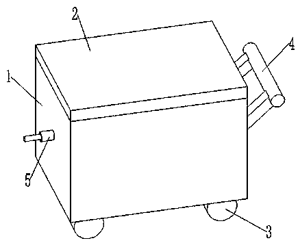
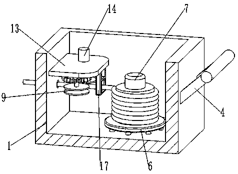
[0032] like Figure 1-Figure 5 The shown optical fiber release device for underground mobile equipment in coal mines includes a box body 1, a box cover 2, a turntable 6, a column 7, a first guide wheel 8, a second guide wheel 9, a lead tube 5 and a power mechanism.

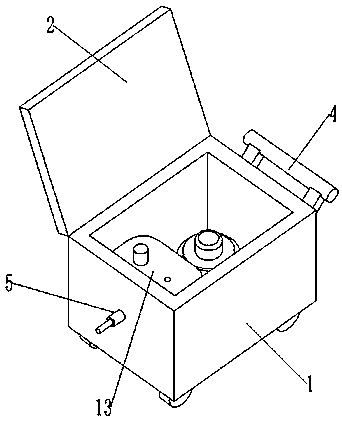
[0033] like figure 1 and figure 2 As shown, the box body 1 defines an accommodating cavity with an open top, and the box cover 2 is rotatably connected with the box body 1, and the box cover 2 is suitable for covering the open end of the accommodating cavity.

[0034] Specifically, the box body 1 is roughly square in shape, and the box cover 2 is a square thin plate structure. By opening the box cover 2, the optical fiber line package can be placed in the box body 1, or the optical fiber line package can be replaced. The case cover 2, the case cover 2 can cover the open end of the accommodating chamber, so as to prevent dust and the like from entering the case body 1 when working underground.

[0035] like i...

Embodiment 2

[0046] Embodiment 2 is a further improvement to Embodiment 1.

[0047] like Figure 1-Figure 5 As shown, the box body 1 defines an accommodating cavity with an open top, the box cover 2 is rotatably connected with the box body 1, the box cover 2 is suitable for covering the open end of the accommodating cavity, the bottom of the box body 1 is provided with a roller 3, and the bottom of the box body 1 One side is provided with a push handle 4; the turntable 6 is located in the accommodation cavity, the turntable 6 is connected to the box body 1 in rotation, the turntable 6 is provided with a vertical column 7, and the turntable 6 is placed with an optical fiber line package, and the optical fiber line package is arranged on the On the column 7; the first guide wheel 8 and the second guide wheel 9 are all installed on the inner side wall of the accommodating chamber and connected with the box 1 in rotation, the first guide wheel 8 and the second guide wheel 9 are arranged opposi...


PUM


Abstract

The invention relates to optical fiber releasing equipment of underground moving equipment of a coal mine. The equipment comprises a box body, a box cover, a turntable, a stand column, a first guide wheel, a second guide wheel, a lead pipe and a power mechanism; an accommodating cavity with an open top is defined by the box body, the box cover is rotatably connected with the box body, the turntable is positioned in the accommodating cavity, the turntable is rotatably connected with the box body, the vertical stand column is arranged on the turntable, an optical fiber wire package is placed onthe turntable, and the optical fiber wire bag sleeves the stand column; the first guide wheel and the second guide wheel are arranged on the inner side wall of the accommodating cavity and are rotatably connected with the box body, and the outer wheel periphery of the first guide wheel and the outer wheel periphery of the second guide wheel are spaced and define a guide space; the power mechanismis connected with the first guide wheel and the second guide wheel, the power mechanism is suitable for driving the first guide wheel and the second guide wheel to rotate, and the rotation directionsof the first guide wheel and the second guide wheel are opposite; and the lead pipe is arranged on the outer side wall of the box body, and optical fibers of the optical fiber wire package penetrate through the guide space and the lead pipe and protrude outwards.

Description

technical field [0001] The invention relates to the field of mining equipment, in particular to an optical fiber release device for underground mobile equipment in coal mines. Background technique [0002] The underground environment of coal mines is complex. At present, underground communication is mainly wired communication, and optical fiber communication equipment is a mainstream mode of underground wired communication. For mines under normal conditions, the communication optical fiber is often laid when the mine is built, but after an accident, the pre-laid optical fiber is often destroyed; or for communication that needs to be moved underground Devices, especially small mobile devices, do not have the ability to drag cables or optical fibers due to their own power. [0003] A patent with the application number CN201310448325.1 discloses an optical fiber release device for underground mobile equipment in coal mines. Shell, introduction device, and lower cylinder; the ...

Claims


Application Information

Patent Timeline
Patent Type & Authority Applications(China)
IPC IPC(8): B65H49/28B65H57/14B65H49/32G02B6/50
CPCB65H49/28B65H49/32B65H57/14B65H2701/32G02B6/50
Inventor 胡增永
Owner 胡增永
Why Eureka
Try Eureka