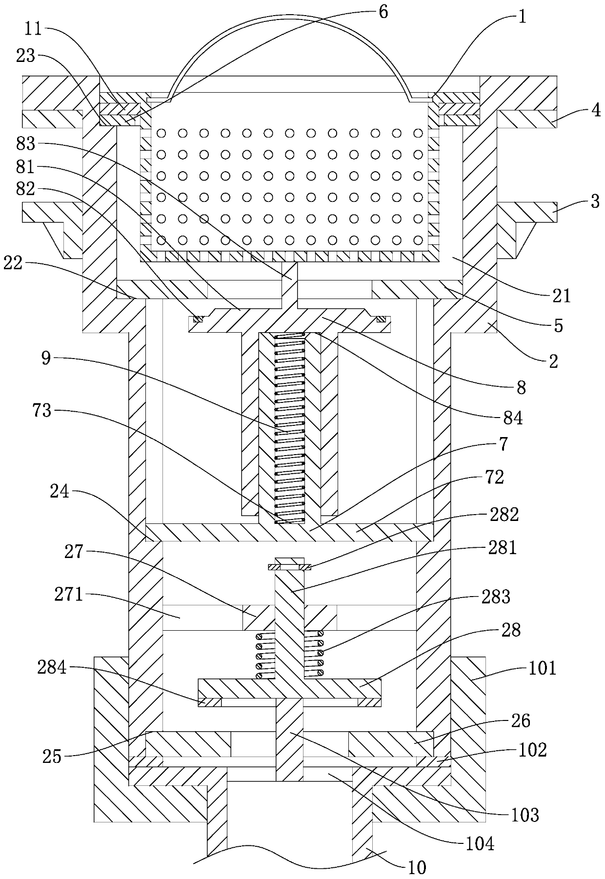
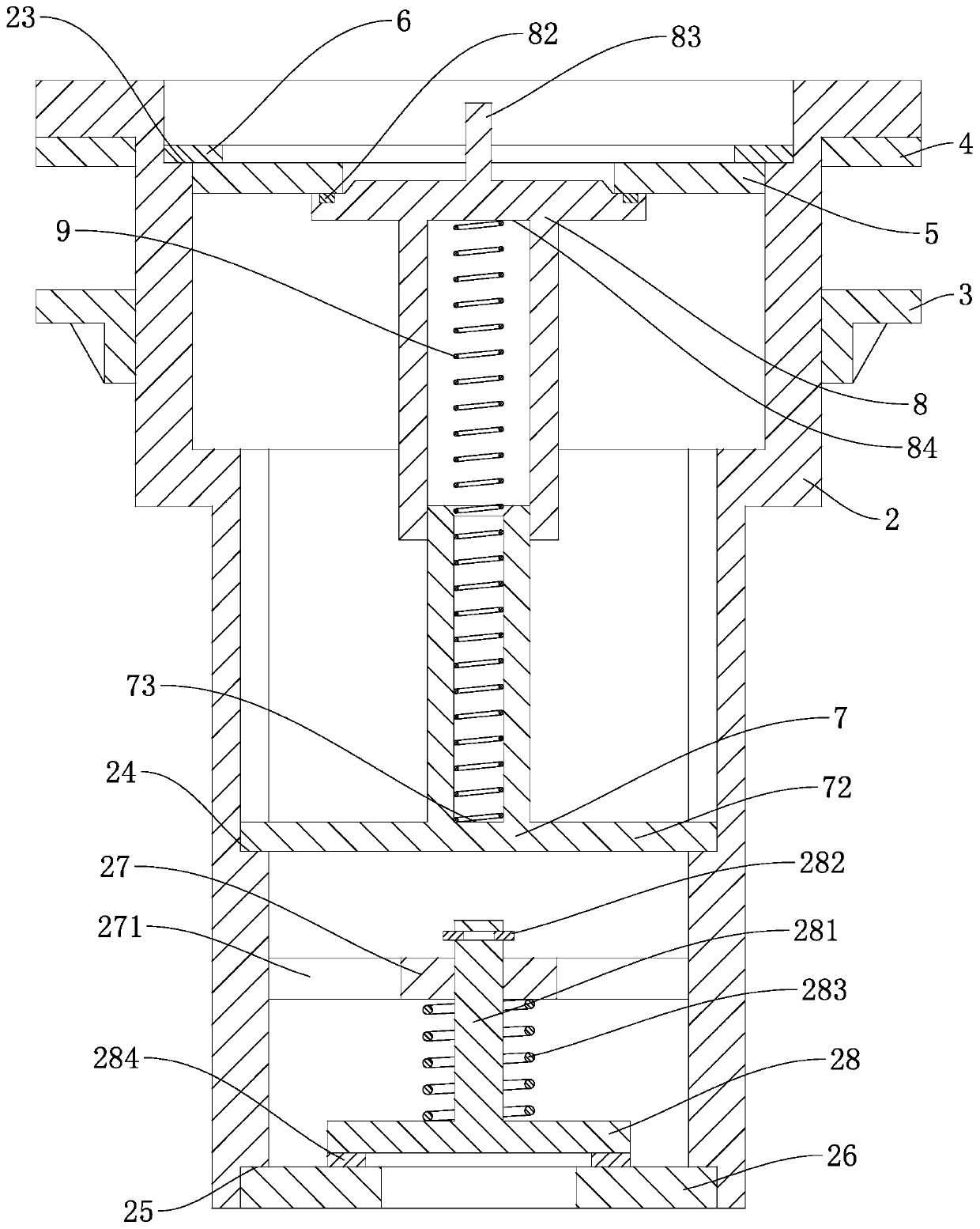
Sink drainage assembly with automatic blocking function

A technology for drainage components and sinks, applied in water supply installations, indoor sanitary piping installations, buildings, etc., can solve problems such as space pollution, pressure sleeves detached from the shell, and user inconvenience, and achieve the effect of avoiding pollution.

Active Publication Date: 2020-06-16
威海云之卫智能科技有限公司
View PDF6 Cites 1 Cited by
  • Summary
  • Abstract
  • Description
  • Claims
  • Application Information

AI Technical Summary

Problems solved by technology

However, during the draining process of the current sink drainage assembly, if there is an unexpected situation in which the drain pipe breaks away from the housing (because the current drain pipe is pressed tightly on the housing by a compression sleeve, and the compression sleeve and the housing are all made of plastic material It is easy to appear that the pressure sleeve is separated from the shell during the long-term use of the pressure sleeve and the shell. Once the pressure sleeve is detached from the shell, the drain pipe will appear to be detached from the shell). The discharged water will directly fall into the space below the sink, thereby polluting the space below the sink, so that the user needs to clean it up, which will cause inconvenience to the user

Method used


Image

  • Sink drainage assembly with automatic blocking function
  • Sink drainage assembly with automatic blocking function
  • Sink drainage assembly with automatic blocking function

Examples


Embodiment Construction

[0015] A number of embodiments of the present invention will be disclosed in the following figures. For the sake of clarity, many practical details will be described together in the following description. It should be understood, however, that these practical details should not be used to limit the invention. That is, in some embodiments of the invention, these practical details are not necessary. In addition, for the sake of simplifying the drawings, some well-known and commonly used structures and components will be shown in a simple schematic manner in the drawings.

[0016] In addition, in the present invention, descriptions such as "first", "second" and so on are used for description purposes only, and do not refer to the meaning of order or sequence, nor are they used to limit the present invention, but are only for the purpose of distinguishing the following The components or operations described by the same technical terms are only used, but should not be understood a...


PUM


Abstract

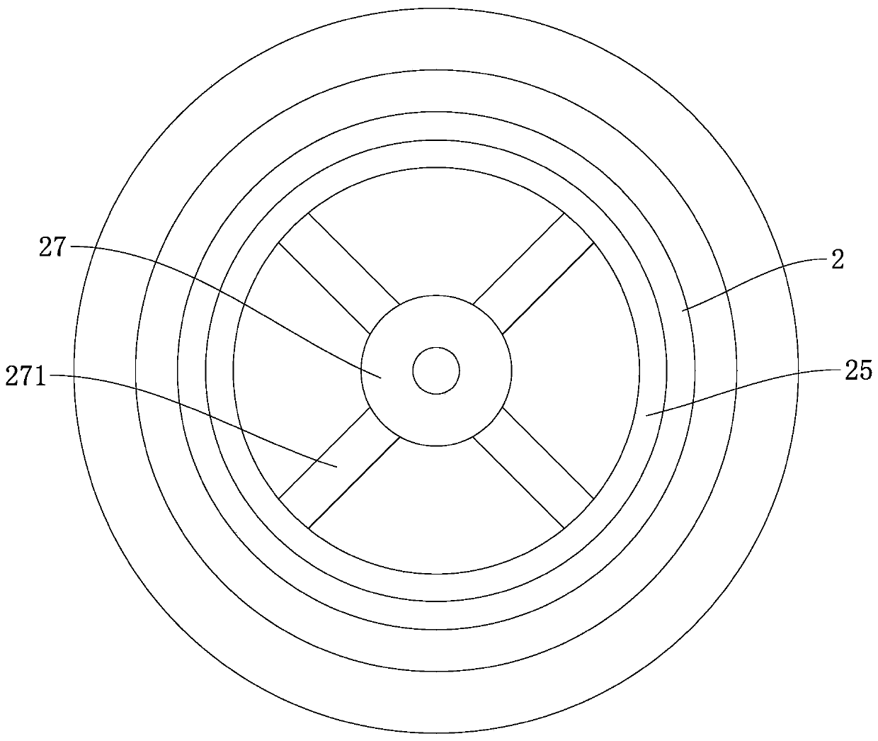
The invention discloses a sink drainage assembly with an automatic blocking function. The assembly comprises a filter basket and a shell. A drainage pipe is connected to the lower end of the shell. Afourth annular step is arranged at the inner circumferential wall of the lower end of the shell. A limiting ring is in threaded connection with the interior of the fourth annular step. A pressing sleeve sleeves the drainage pipe. The pressing sleeve is in threaded connection with the outer circumferential wall of the shell. A second sealing ring is embedded between the upper end face of the drainage pipe and the lower end face of the shell. A supporting disc is arranged in the portion, above the limiting ring, of the shell. A pressing disc is arranged below the supporting disc. A sliding rod is integrally formed in the middle of the upper end face of the pressing disc. The sliding rod movably penetrates through the supporting disc and then stretches out of the supporting disc to be cooperatively clamped to a clamping spring. A second spring sleeves the portion, between the supporting disc and the pressing disc, of the sliding rod. A third sealing ring is attached to the edge of the lower end face of the pressing disc. A push rod is arranged at the inner side of the drainage pipe. When the drainage pipe inside the sink drainage assembly is prone to be disengaged from the shell, theshell can automatically achieve the function of stopping draining.

Description

technical field [0001] The invention relates to the technical field of a water tank drainage assembly, in particular to a water tank drainage assembly with an automatic sealing function. Background technique [0002] The sink drain assembly is an indispensable part of the sink. The current sink drain assembly mainly includes a filter basket and a shell. The bottom surface of the upper end of the body is fitted with a sealing ring for contacting the inner bottom of the water tank to seal the housing and the water tank, the lower end of the housing is connected with a drain pipe, and the upper end of the housing is provided with a cavity for accommodating a filter basket. After the water tank drainage assembly is assembled with the water tank, the sealing ring is pressed against the inner bottom of the water tank, and the pressure ring is pressed against the outer bottom of the water tank. However, during the draining process of the current sink drainage assembly, if there is...

Claims


Application Information

Patent Timeline
IPC IPC(8): E03C1/262E03C1/23
CPCE03C1/23E03C1/262
Inventor 沈鑫光
Owner 威海云之卫智能科技有限公司
Why Eureka
Try Eureka