Capacitive sensor stability testing device

A technology for capacitive sensor and stability testing, applied in instruments and other directions, can solve problems such as capacitive sensor detection, and achieve the effects of accurate testing, simple structure, and high testing accuracy

Active Publication Date: 2020-06-16
NAT INST OF METROLOGY CHINA
View PDF16 Cites 1 Cited by
  • Summary
  • Abstract
  • Description
  • Claims
  • Application Information

AI Technical Summary

Problems solved by technology

At present, there are capacitive sensor manufacturers claiming that their products can achieve a display value drift range of no more than 1nm within 4 hours, but there is no corresponding detection device that can accurately detect the stability of capacitive sensors

Method used


Image

  • Capacitive sensor stability testing device
  • Capacitive sensor stability testing device
  • Capacitive sensor stability testing device

Examples


Embodiment 1

[0033] Embodiment 1: Stability test of capacitive sensor with standard size.

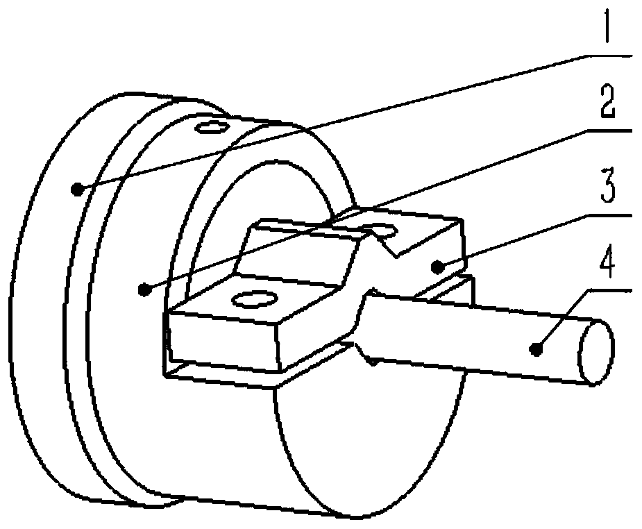
[0034] like figure 1 As shown, the stability test method of the capacitive sensor of the present embodiment is as follows:

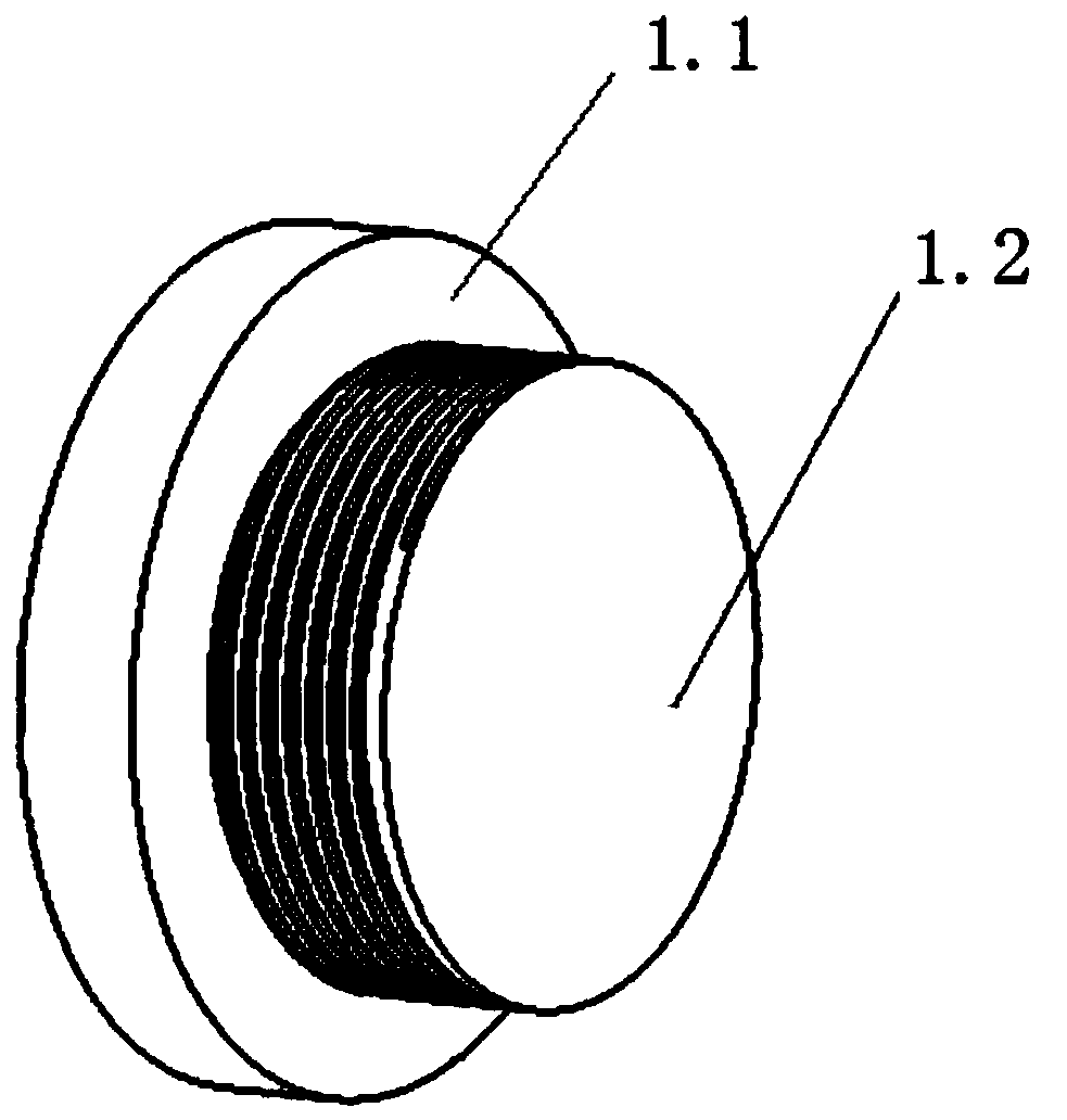
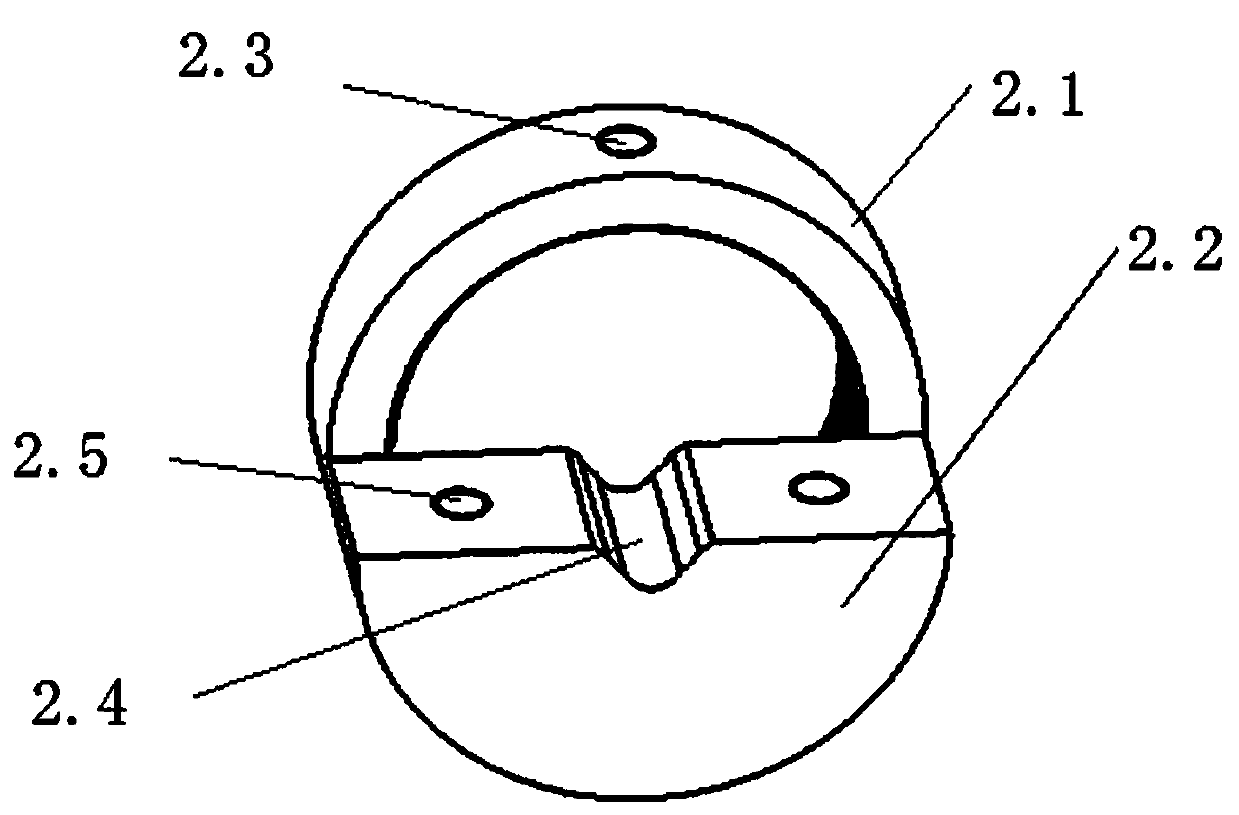
[0035] S1. Tighten the external thread on the peripheral surface of the second cylinder 1.2 and the internal thread on the inner surface of the connecting ring 2.1 to complete the connection between the base 1 and the connecting body 2;

[0036] S2. Put the capacitive sensor 4 into the first through groove 2.4 of the connecting body 2. The working surface of the capacitive sensor 4 faces the base 1. By rotating the second cylinder 1.2, the working surface of the capacitive sensor 4 is aligned with the second cylinder 1.2. The distance between the grinding surfaces remains within the working range of the capacitive sensor 4;

[0037] S3, tighten the second screw in the threaded through hole 2.3 of the connecting body 2;

[0038]S4. Fasten the bottom of the upper cover 3 to t...

Embodiment 2

[0040] Embodiment 2: Stability test of a micro-sized capacitive sensor.

[0041] like Figure 5 As shown, the stability test method of the capacitive sensor of the present embodiment is as follows:

[0042] S1. Tighten the external thread on the peripheral surface of the second cylinder 1.2 and the internal thread on the inner surface of the connecting ring 2.1 to complete the connection between the base 1 and the connecting body 2;

[0043] S2. Put the capacitive sensor 4 into the first through groove 2.4 of the connecting body 2. The working surface of the capacitive sensor 4 faces the base 1. By rotating the second cylinder 1.2, the working surface of the capacitive sensor 4 is aligned with the second cylinder 1.2. The distance between the grinding surfaces remains within the working range of the capacitive sensor 4;

[0044] S3. Tighten the screw in the threaded through hole 2.3 of the connecting body 2;

[0045] S4. Buckle the top of the upper cover 3 downwards onto th...


PUM


Abstract

The invention discloses a capacitive sensor stability testing device, which comprises a base, a connecting body and an upper cover, wherein the base is detachably connected with the connecting body, and the upper cover is detachably connected with the connecting body; the connecting body comprises a connecting ring, the connecting ring is fixedly connected with a mounting base, and the connectingring and the mounting base are integrally formed; a first through groove is formed in the mounting base, and a plurality of grooves with different sizes are formed in the inner walls of the first through groove; a capacitance sensor is placed in the first through groove; a limiting block is arranged on the top surface of the upper cover, and a second through groove is formed in the bottom surfaceof the upper cover; and the upper cover is detachably connected with the mounting base. The capacitive sensor stability testing device is simple in structure, is convenient to clamp and disassemble, and can meet the stability testing demands of capacitive sensors with different diameters; and the test surface is a grinding surface, the grinding grade is K grade, and the detection precision of thestability of the capacitive sensor is effectively improved.

Description

technical field [0001] The invention relates to the field of test and measurement, in particular to a capacitance sensor stability test device. Background technique [0002] A capacitive sensor is a device that converts the measured change into a change in capacitance, which itself is a variable capacitor. Because the capacitive sensor has the characteristics of simple structure, small size, good dynamic response, high sensitivity, high resolution, and non-contact measurement, it is widely used in displacement, acceleration, vibration, pressure, pressure difference, liquid level, etc. Content detection field. [0003] As the performance of capacitive sensors improves gradually, its good stability is crucial to the improvement of the overall performance. At present, there are capacitive sensor manufacturers claiming that their products can achieve a display value drift range of no more than 1nm within 4 hours, but there is no corresponding detection device that can accurate...

Claims


Application Information

Patent Timeline
Patent Type & Authority Applications(China)
IPC IPC(8): G01D18/00
CPCG01D18/00
Inventor 崔建军李建双王冬闵帅博崔京远沈雪萍
Owner NAT INST OF METROLOGY CHINA
Why Eureka
Try Eureka