A mid-infrared Bragg optical fiber and its gas qualitative and quantitative detection device
A Bragg optical fiber, quantitative detection technology, applied in the direction of measuring devices, cladding optical fibers, multi-layer core/clad optical fibers, etc., can solve the problems of optical fiber interface loss, detection result error, etc., and achieve low loss transmission, low interference, Effect of Improving Measurement Accuracy
- Summary
- Abstract
- Description
- Claims
- Application Information
AI Technical Summary
Problems solved by technology
Method used
Image
Examples
Embodiment 1
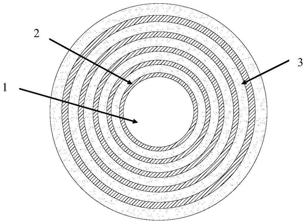
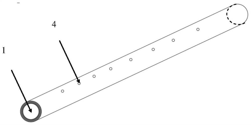
[0049] 1. A mid-infrared Bragg optical fiber, the schematic cross-section of which is shown in figure 1 , see side view figure 2 , the described mid-infrared Bragg fiber is an optical fiber with a sulfur-tellurium hollow-core Bragg structure; the mid-infrared Bragg fiber is made of tellurate TZPPN glass layer 2 and chalcogenide As 2 S 5 The cladding area formed by lamination of glass layers 3 and the hollow core area 1 surrounded by the cladding area; wherein, the cladding area is a Bragg structure layer, the first layer of which is a tellurate TZPPN glass layer 2, Chalcogen As 2 S 5 The glass layer 3, by analogy, consists of a tellurite glass layer and a chalcogenide glass layer as a stack, and the Bragg structure layer has five sets of stacks.
[0050] Two rows of through holes 4 are set on the side of the mid-infrared Bragg fiber, each through hole 4 is arranged along the central axis direction of the mid-infrared Bragg fiber, and is evenly arranged on a straight line ...
Embodiment 2
[0066] 1. A mid-infrared Bragg optical fiber with a sulfur-tellurium hollow-core Bragg structure, including a Bragg structure layer and a hollow core area surrounded by a Bragg structure layer. The Bragg structure layer is a stack of tellurate glass layers and chalcogenide glass layers alternately spaced. Cloth; Wherein, the present embodiment selects, and the composition of described tellurite glass layer is TeO 2 ·ZnO·PbO·PbF 2 ·Na 2 O(TZPPN), the composition of the chalcogenide glass layer is As 2 S 5 .
[0067] According to its refractive index comparison, this embodiment designs the chalcogenide glass layer as the first layer of the Bragg structure;
[0068] Specifically, the cladding region of the mid-infrared Bragg optical fiber includes at least 6 layers of glass layers, at least 3 layers of tellurite glass layers and 3 layers of chalcogenide glass layers, distributed in layers. The thickness ratio of the tellurate glass layer and the chalcogenide glass layer is a...
Embodiment 3
[0076] 1. A mid-infrared Bragg optical fiber, the described mid-infrared Bragg optical fiber is an optical fiber with a sulfur-tellurium hollow-core Bragg structure; the mid-infrared Bragg optical fiber is composed of a cladding region formed by lamination of a tellurite glass layer and a chalcogenide glass layer and The hollow area surrounded by the cladding area; wherein, the cladding area is a Bragg structure layer, the first layer of which is a chalcogenide glass layer, the second layer is a tellurite glass layer, and so on, with a layer of chalcogenide glass layer The glass layer and one tellurite glass layer are one set of stacks, and the Bragg structure layer has five sets of stacks.
[0077] Two rows of through holes are arranged on the side of the mid-infrared Bragg optical fiber, each through hole is arranged along the central axis of the mid-infrared Bragg optical fiber and evenly arranged on a straight line parallel to the central axis; The holes are evenly distrib...
PUM
 Abstract
Description
Claims
Application Information
 - R&D
- Intellectual Property
- Life Sciences
- Materials
- Tech Scout
- Unparalleled Data Quality
- Higher Quality Content
- 60% Fewer Hallucinations
Browse by: Latest US Patents, China's latest patents, Technical Efficacy Thesaurus, Application Domain, Technology Topic, Popular Technical Reports.
© 2025 PatSnap. All rights reserved.Legal|Privacy policy|Modern Slavery Act Transparency Statement|Sitemap|About US| Contact US: help@patsnap.com


