Electronic device

A technology of electronic devices and electronic units, applied to instruments, static indicators, etc., can solve the problems of different brightness and lower quality of display equipment

Active Publication Date: 2020-06-16
INNOLUX CORP
View PDF25 Cites 3 Cited by
  • Summary
  • Abstract
  • Description
  • Claims
  • Application Information

AI Technical Summary

Problems solved by technology

However, due to the difference in the manufacturing process, the luminance of the light-emitting compone

Method used


Image

  • Electronic device
  • Electronic device
  • Electronic device

Examples


Embodiment Construction

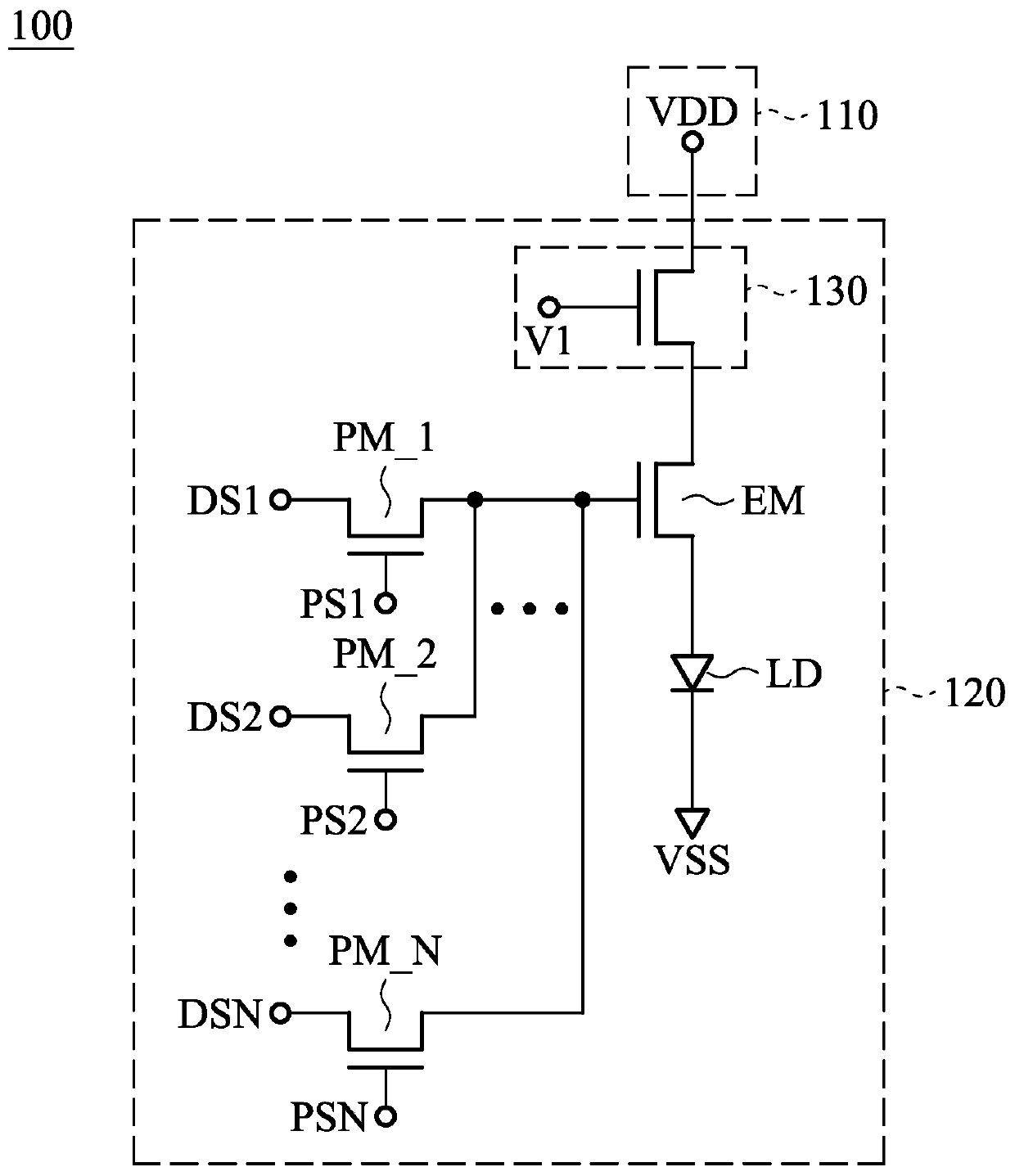
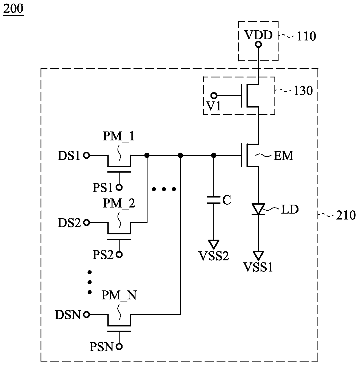
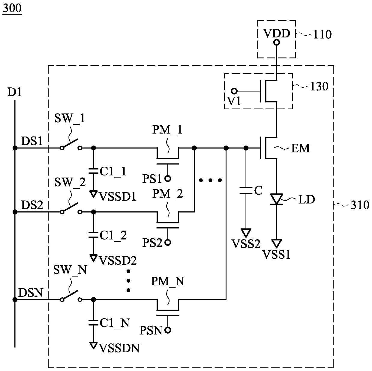
[0064] In order to make the purpose, features and advantages of the present invention more comprehensible, the following specifically cites the embodiments, together with the accompanying drawings, for a detailed description. In order to make the readers easy to understand and the drawings concise, the several drawings in the present disclosure may only depict a part of the whole device, and the specific components in the drawings are not drawn according to the actual scale.

[0065] The description of the present invention provides different examples to illustrate the technical features of different implementations of the present invention. Wherein, the configuration, quantity and size of each component in the embodiment are for illustration purposes, not to limit the present invention. In addition, if the numbering of components in the embodiment and the drawings is repeated, it is for the purpose of simplifying the description, and does not imply the correlation between dif...


PUM


Abstract

The present invention provides an electronic device. The electronic device includes a power source unit and an electronic unit. The electronic unit includes a first switch, a light-emitting unit, anda plurality of pulse switches. The first switch is coupled to the power source unit, and the first switch has a gate electrode. The light-emitting unit is coupled to the first switch. The plurality ofpulse switches are coupled to the gate electrode of the first switch. Therefore, the brightness of the light-emitting unit may be effectively controlled to improve the quality of the electronic device.

Description

technical field [0001] The embodiments of the present invention relate to an electronic device, in particular to an electronic device capable of controlling the brightness of a light emitting unit. Background technique [0002] The light-emitting components of known electronic devices can generate light with brightness corresponding to gray levels. However, due to differences in manufacturing processes, the luminance displayed by the light-emitting components may be different under the same driving voltage, which may degrade the quality of the display device. Therefore, a new circuit structure design is needed to improve the aforementioned problems. Contents of the invention [0003] In order to solve the above-mentioned problem that the brightness of the light-emitting components is different under the same driving voltage, which may reduce the quality of the display device, the present invention provides an electronic device to control the brightness of the light-emitti...

Claims


Application Information

Patent Timeline
IPC IPC(8): G09G3/32G09G3/3225G09G3/36
CPCG09G3/32G09G3/3225G09G3/36G09G2320/0626
Inventor 石明家曾名骏韦忠光丁景隆
Owner INNOLUX CORP
Why Eureka
Try Eureka