Feeding device for animal husbandry

A technology of animal husbandry and walking devices, which is applied in animal husbandry, animal feeding devices, applications, etc., and can solve the problems of feed overflow and waste, discontinuous areas of feeding troughs, etc.

Inactive Publication Date: 2020-06-19
张仲萍 +2
View PDF6 Cites 3 Cited by
  • Summary
  • Abstract
  • Description
  • Claims
  • Application Information

AI Technical Summary

Problems solved by technology

[0005] The invention provides a feeding device for animal husbandry, which can solve the problem in the prior art that the areas of feeding troughs required for feeding are not continuous, and continuous feeding causes a large amount of overflow and waste of feed

Method used


Image

  • Feeding device for animal husbandry
  • Feeding device for animal husbandry
  • Feeding device for animal husbandry

Examples


specific Embodiment 1

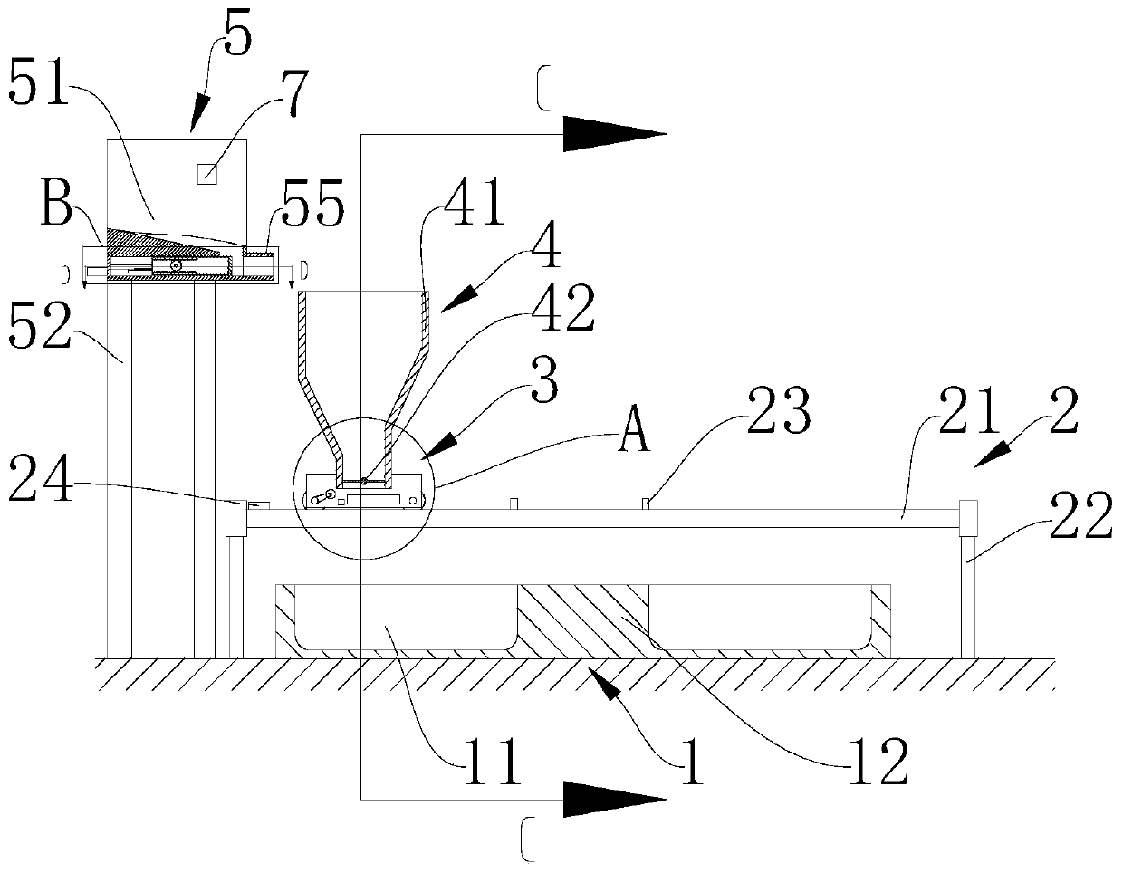
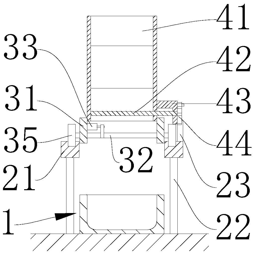
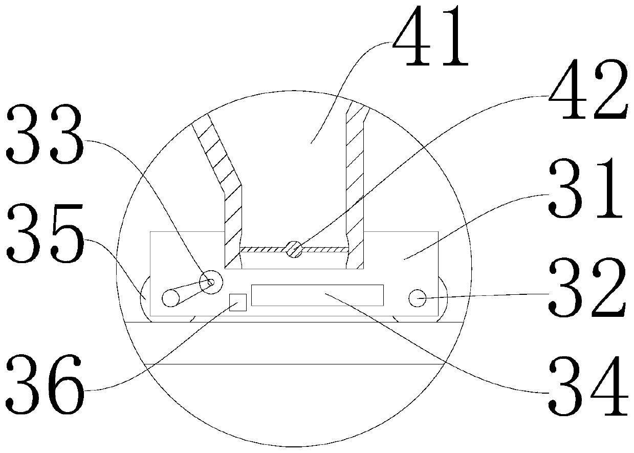
[0031] like Figure 1 to Figure 6 As shown, an animal husbandry feeding device provided in an embodiment of the present invention includes a feed trough 1, a frame 2, a traveling device 3 and a hopper 4, wherein:

[0032] The feed trough 1 includes a feeding area 11 and a partition area 12, and the partition area 12 is located inside the feed trough 1;

[0033] The frame 2 includes a sliding slot 21, a column 22 and a toggle block 23. The two sliding slots 21 are arranged in parallel. The sliding slot 21 has a limit slot from the top for the installation and travel limit of the traveling device 3. The four columns 22 One end is fixedly connected to the ground, and the other ends of the four uprights 22 are fixedly connected to the end points of the two sliding grooves 21 respectively, which play a supporting role and do not interfere with the movement of the walking device 3. Several toggle blocks 23 are screwed and connected to a On the outside of the sliding slot 21, the sl...

specific Embodiment 2

[0041] On the basis of the specific embodiment 1, it also includes a storage device 5. The storage device 5 includes a storage box 51, a support column 52, an electric push rod 53, a partition 54, a discharge port 55, a first rack 56, a second A gear 57, a second gear 58, a second rack 59 and a second button 60, the frame 2 further includes a travel switch 24, one end of the support column 52 is fixedly connected to the ground, and the other end of the support column 52 is fixedly connected to the storage material Box 51, the discharge port 55 is located at the bottom of the storage box 51 and penetrates into the inner cavity of the storage box 51, the electric push rod 53 is fixedly connected to the side wall of the storage box 51, and the output end of the electric push rod 53 is fixedly connected to the first A rack 56, the side wall of the storage box 51 is provided with a rack slot, and the output end of the electric push rod 53 and the first rack 56 are slidably arranged ...


PUM


Abstract

The invention discloses a feeding device for an animal husbandry and belongs to the field of breeding equipment for the animal husbandry. A feed trough comprises a feeding area and a partition area, poking blocks are detachably connected to the outer side of one sliding groove; walking wheels are in rolling connected with limiting grooves, and a motor is in drive connection with connecting rods; an opening and closing turning plate is rotationally connected to an outlet of a hopper body, a poking piece is fixedly connected to one end of the opening and closing turning plate, positioning beadsand positioning holes are matched for positioning, and the poking blocks and the poking piece are matched for poking. When the feeding device walks above the feeding area, the opening and closing turning plate is opened, a dropping hopper uniformly drops feed in the feeding area; when the feeding device advances to the upper side of the partition area, the poking blocks poke the poking piece to drive the opening and closing turning plate to rotate by 90 degrees, the positioning beads and the positioning holes are matched for positioning, the opening and closing turning plate closes a discharging port of the dropping hopper; and when the feeding device walks to the upper side of the next feeding area, the poking blocks poke the poking piece, the discharging port of the dropping hopper is opened to uniformly drop feed.

Description

technical field [0001] The invention relates to the field of animal husbandry breeding equipment, in particular to a feeding device for animal husbandry. Background technique [0002] Animal husbandry is the use of domesticated animals, such as livestock and poultry, through artificial breeding and breeding to convert grass and feed and other plant energy into animal energy to obtain meat, eggs, milk, wool, cashmere, hides, The production sector of livestock products such as silk and medicinal materials is different from self-sufficient livestock breeding. The main characteristics of animal husbandry are centralized, large-scale, and profit-making production purposes. In the process of animal husbandry, it is necessary to use a water feeding device to feed the livestock. [0003] After searching, the Chinese Patent Publication (Announcement) No. CN209788146U discloses a feed feeding device for animal husbandry, which includes a feed trough and a storage hopper arranged on t...

Claims


Application Information

Patent Timeline
Patent Type & Authority Applications(China)
IPC IPC(8): A01K5/02
CPCA01K5/0225Y02A40/70
Inventor 不公告发明人
Owner 张仲萍
Why Eureka
Try Eureka