Platform surface cleaning mechanism

A technology for cleaning mechanisms and countertops, applied in cleaning methods and utensils, chemical instruments and methods, etc., can solve the problems of short maintenance cycle, time-consuming and labor-intensive, secondary pollution, etc.

Pending Publication Date: 2020-06-19
苏州科韵激光科技有限公司
View PDF0 Cites 1 Cited by
  • Summary
  • Abstract
  • Description
  • Claims
  • Application Information

AI Technical Summary

Problems solved by technology

[0004] First, the cleaning effect of the platform surface is not good, and it is easy to cause secondary pollution;
[0005] Second, the maintenance cycle is short, the maintenance cost is high, and it is time-consuming and laborious

Method used


Image

  • Platform surface cleaning mechanism
  • Platform surface cleaning mechanism
  • Platform surface cleaning mechanism

Examples


Embodiment approach 1

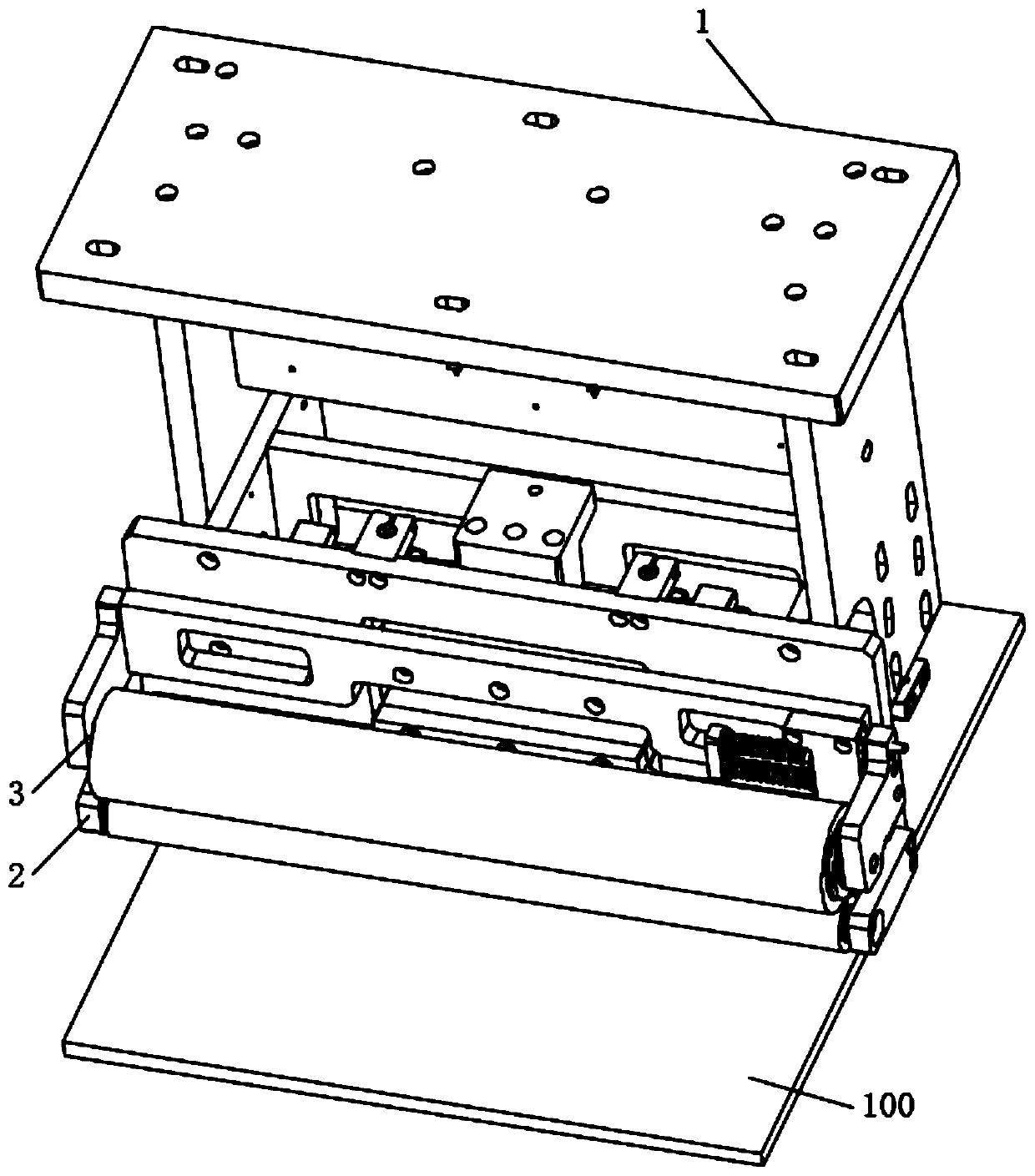
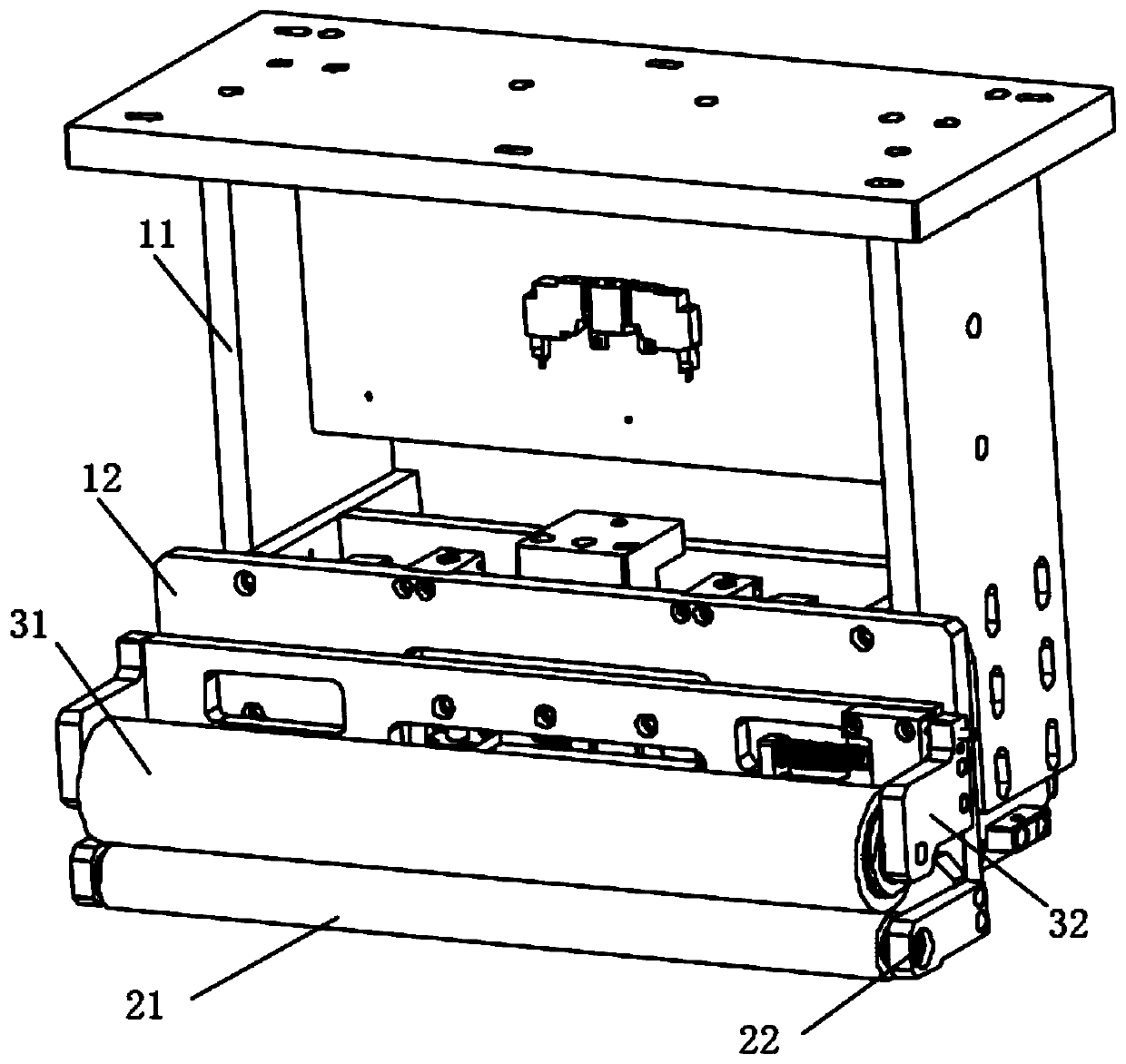
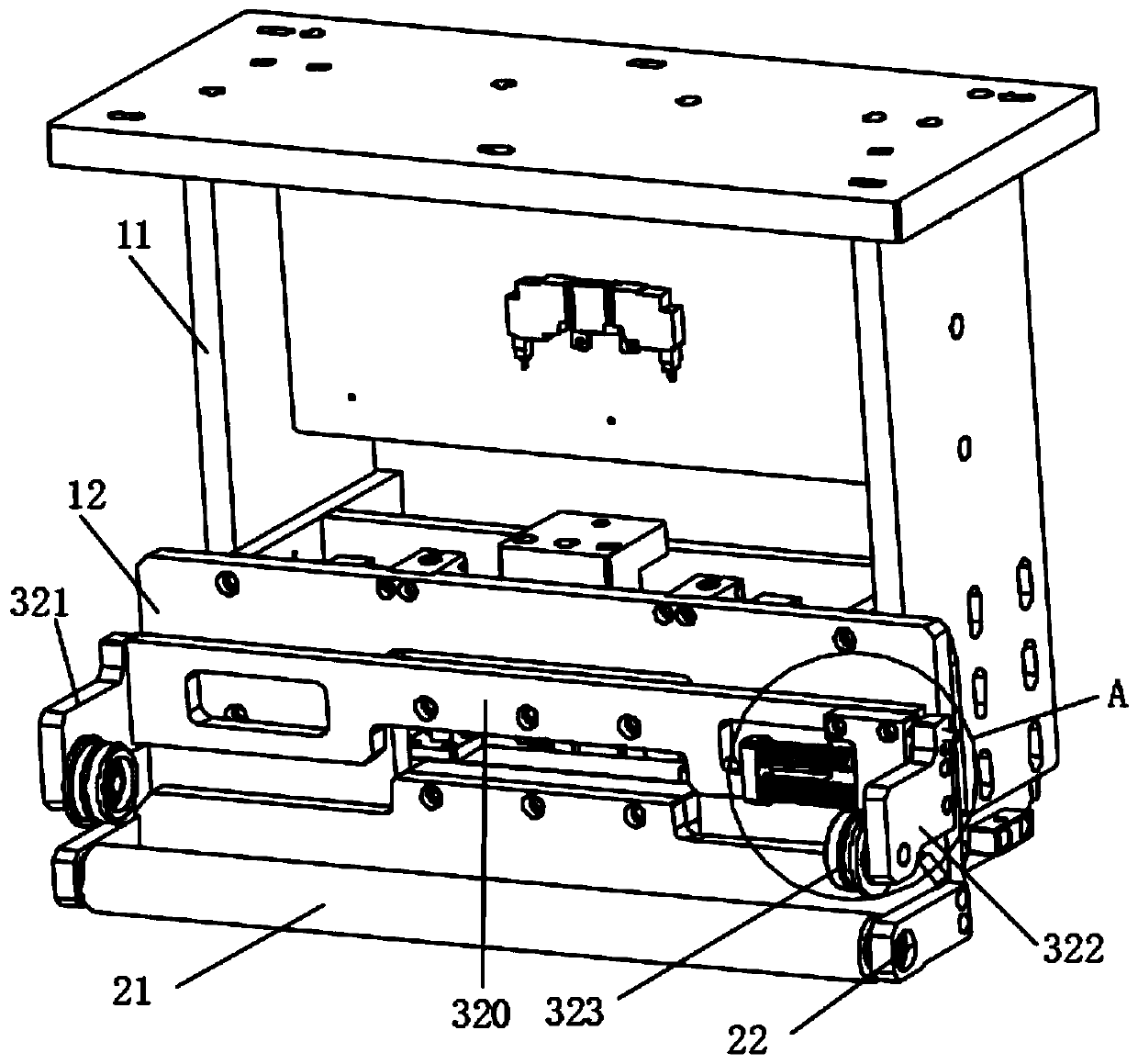
[0056] see figure 1 and figure 2 , this embodiment provides a countertop cleaning mechanism. The table cleaning mechanism can clean up the dust on the platform 100, including: a main body frame 1; a cleaning assembly 2, including a cleaning roller 21, and the roller surface of the cleaning roller 21 is provided with a viscous layer for cleaning the platform 100; a dust collection assembly 3, including Dust collection roller 31, the roller surface of dust collection roller 31 is provided with the viscous layer that is used for cleaning cleaning roller 21; Connection assembly 4, comprises elastic member 41, and cleaning assembly 2 is connected to dust collection assembly 3 by elastic member 41 (referring to Figure 7 ); the drive assembly 5, including the driver 51, the driver 51 is located on the main body frame 1, and can drive the dust collecting roller 31 to be in rolling contact with the cleaning roller 21 (see Figure 7 ).

[0057] Specifically, the axes of the cleanin...

Embodiment approach 2

[0082] This embodiment provides another countertop cleaning mechanism, which is basically the same as the countertop cleaning mechanism in Embodiment 1, the differences are:

[0083] Optionally, the driver 51 includes an oil cylinder, and the driving rod 511 is a piston rod inserted in the oil cylinder; or, the driver 51 includes a linear driver, and the driving rod 511 is an electric push rod driven by a motor.

Embodiment approach 3

[0085] This embodiment provides another countertop cleaning mechanism, which is basically the same as the countertop cleaning mechanism in Embodiment 1, the differences are:

[0086] Guide member 42 comprises slide rail, and slide rail is installed on the front plate 1201, and slide block is respectively installed on the first mount base 20 and the second mount base 30; Slide block can slide along slide rail, and first mount base 20 and second mount base The mounting bases 30 are matched to the slide rails respectively through the sliders; the length direction of the slide rails is the extending direction of the guide member 42 .


PUM


Abstract

The invention relates to the technical field of equipment maintenance, and discloses a platform surface cleaning mechanism. The platform surface cleaning mechanism comprises a main frame, a cleaning assembly, a dust collection assembly, a connecting assembly and a driving assembly, wherein the cleaning assembly comprises a cleaning roller; a viscous layer used for cleaning a platform is arranged on the roller surface of the cleaning roller; the dust collection assembly comprises a dust collection roller; a viscous layer used for cleaning the cleaning roller is arranged on the roller surface ofthe dust collection roller; the connecting assembly comprises an elastic part; the cleaning assembly is connected with the dust collection assembly through the elastic part; the driving assembly comprises a driver; and the driver is arranged on the main frame, and can drive the dust collection roller to be in rolling contact with the cleaning roller. According to the platform surface cleaning mechanism, the dust collection roller can be in rolling contact with the cleaning roller, the cleaning roller can be in rolling contact with the platform, dust on the platform can be stuck by the dust collection roller after being stuck by the cleaning roller, and dust cleaned by the cleaning roller is transferred onto the dust collection roller; and the viscous layer on the dust collection roller ismanually changed regularly to keep the surface of the cleaning roller clean, the cleaning roller can continuously clean dust on the platform, and the surface of the platform is not liable to scratch.

Description

technical field [0001] The invention relates to the technical field of equipment maintenance, in particular to a table cleaning mechanism. Background technique [0002] In recent years, with the continuous development and progress of electronic products, touch screen products have also been applied and promoted in a wider range. At present, the thickness of touch screens on the market is getting thinner and thinner, and the processing time is getting shorter and shorter; during the processing, the particles generated by the touch screen are also easy to adhere to the processing platform. [0003] However, the existing cleaning methods for the processing platform mainly include regular manual cleaning or blowing cleaning, etc., and the main problems are: [0004] First, the cleaning effect of the platform surface is not good, and it is easy to cause secondary pollution; [0005] Second, the maintenance cycle is short, the maintenance cost is high, and it is time-consuming a...

Claims


Application Information

Patent Timeline
Patent Type & Authority Applications(China)
IPC IPC(8): B08B7/00B08B13/00
CPCB08B7/0028B08B13/00
Inventor 陈则立黄巍巍陆昱成
Owner 苏州科韵激光科技有限公司
Why Eureka
Try Eureka