Boring device for automobile motor processing

A technology for automobiles and double-axis motors, applied in positioning devices, feeding devices, metal processing equipment, etc., can solve the problems of end cover clamping stability and low drilling efficiency, and achieve stable and accurate drilling process and environmentally friendly drilling The effect of the operation

Inactive Publication Date: 2020-06-19
黄国普
View PDF10 Cites 17 Cited by
  • Summary
  • Abstract
  • Description
  • Claims
  • Application Information

AI Technical Summary

Problems solved by technology

[0003] The patent whose authorized notification number is CN107252908B discloses an automatic drilling device for a motor end cover, which includes a transmission device, a material bin device, a porous drilling device and a finished product bin; the described The silo device includes a positioning rod, a silo support plate, a lower clamping cylinder, an upper clamping cylinder and a material silo device frame; the transmission device includes a processing base plate, a positioning moving plate, a moving ball screw pair, a moving wire Rod motor and transmission device frame; the described multi-hole drill processing device includes a p

Method used


Image

  • Boring device for automobile motor processing
  • Boring device for automobile motor processing
  • Boring device for automobile motor processing

Examples


Embodiment 1

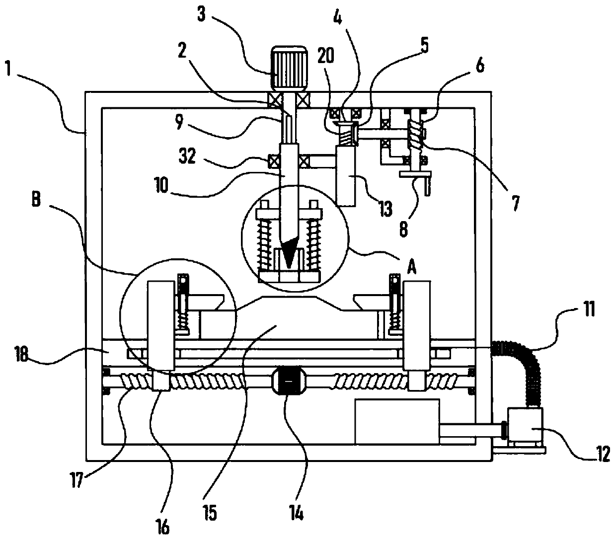
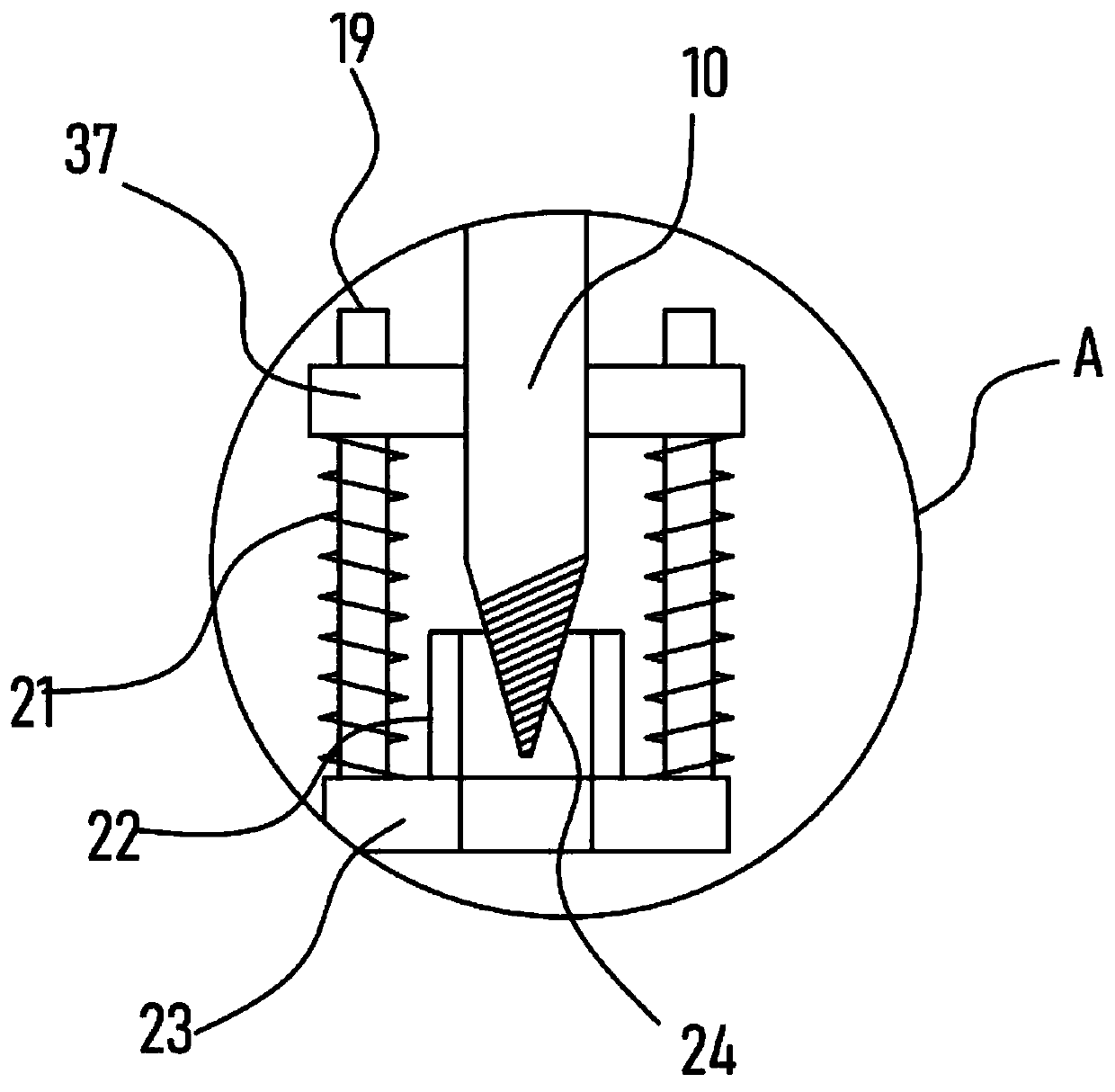
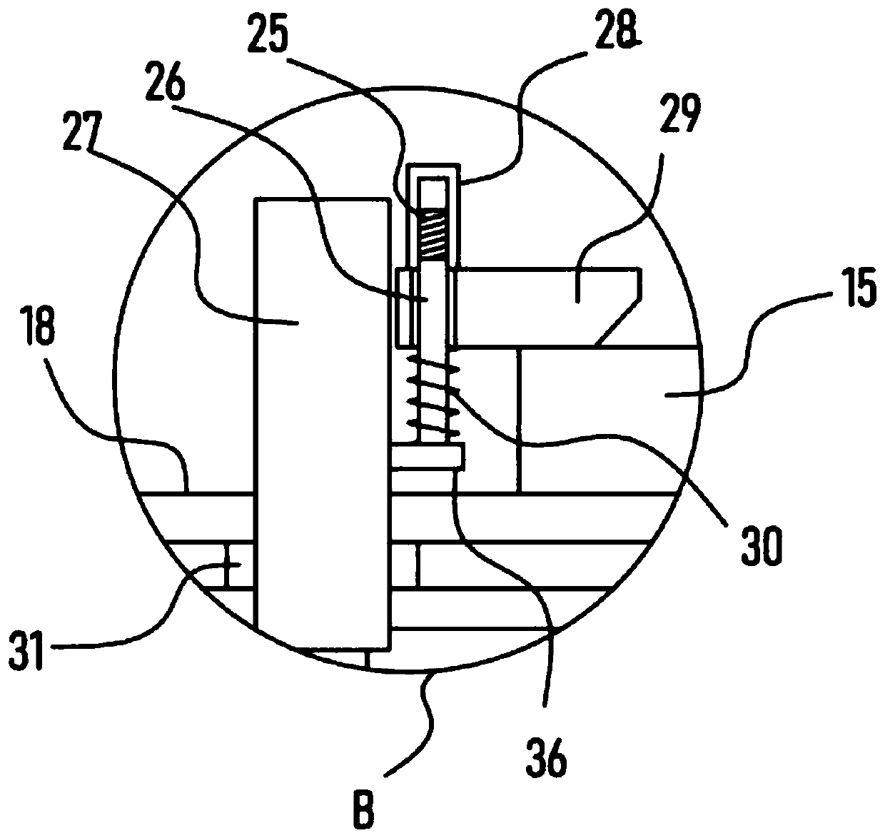
[0025] see Figure 1-4 , a device for processing holes for automobile motors, comprising a support frame 1, a bearing plate 18 is fixedly installed horizontally in the support frame 1, a biaxial motor 14 is fixed on the bottom of the support plate 18, and the biaxial motor 14 is driven and connected to the loading plate. 18 is a slidingly connected opposing translation mechanism, the opposing translation mechanism is provided with a pair of locking mechanisms for clamping and fixing the motor end cover 15, a drive motor 3 is fixed on the top of the support frame 1, and the drive motor 3 The drill bit 24 that is used to drill the motor end cover 15 is connected by a transmission mechanism, and the drill bit 24 is provided with an elastic support mechanism outside, and the support frame 1 is provided with a lifting mechanism for adjusting the lift of the drill bit 24. The support frame 1 There is a dust collection mechanism on it.

[0026] When the motor end cover 15 is drillin...

Embodiment 2

[0032] On the basis of Embodiment 1, in addition, the transmission mechanism of the device includes a transmission bar 2 coaxially fixed with the output shaft of the drive motor 3, and the upper sliding sleeve of the transmission bar 2 is provided with a threaded sleeve 10 fixed to the drill bit 24 at the lower end. The side wall of the rotating shaft 9 is fixed with a transmission bar 2 slidably embedded in the inner wall of the threaded sleeve 10, and the driving motor 3 is set to drive the rotating shaft 9 to rotate, and the rotating shaft 9 drives the threaded sleeve 10 to rotate through the transmission bar 2. When the drill bit 24 rotates thereupon, the lifting mechanism drives the drill bit 24 to move down, so as to realize the perforation effect to the motor end cover 15.

[0033] Specifically, the lifting mechanism includes a lifting plate 32 pivotally connected to the threaded sleeve 10. A vertically arranged threaded sleeve I13 is fixed on the lifting plate 32. The t...


PUM


Abstract

The invention discloses a boring device for automobile motor processing, and relates to the technical field of motor processing. The boring device for automobile motor processing comprises a support frame, wherein a pair of locking mechanisms used for clamping and fixing a motor end cover are arranged on an opposite translation mechanism; a driving motor is fixed on the top of the support frame; an ascending and descending mechanism used for regulating a drill bit to ascend and descend is arranged on the support frame; and a dust collection mechanism is arranged on the support frame. Through the arrangement of the translation mechanism, the face-to-face translation of two sliding frames is realized under the driving effect of a double-shaft motor; the face-to-face movement of the locking mechanism is further realized; the motor end cover can be firmly and reliably locked and fixed; through the arrangement of an elastic support mechanism, the motor end cover can be firmly and reliably pressed and fixed during boring; the boring process of the motor end cover is more stable and precise; through the arrangement of the dust collection mechanism, chippings and dust generated in the boring process can be extracted and absorbed in time; and the efficient and environment-friendly boring operation on the motor end cover is realized.

Description

technical field [0001] The invention relates to the technical field of motor processing, in particular to an automobile motor processing hole opening device. Background technique [0002] Motor English: Electric machinery, commonly known as "motor", refers to an electromagnetic device that realizes the conversion or transmission of electric energy according to the law of electromagnetic induction. The motor is represented by the letter M in the circuit, and the old standard is represented by D. Its main function is to generate driving torque as a power source for electrical appliances or various machines. The generator is represented by the letter G in the circuit. Its main function is Convert mechanical energy into electrical energy. [0003] The patent whose authorized notification number is CN107252908B discloses an automatic drilling device for a motor end cover, which includes a transmission device, a material bin device, a porous drilling device and a finished product...

Claims


Application Information

Patent Timeline
IPC IPC(8): B23B41/00B23B47/18B23Q3/06B23Q11/00
CPCB23B41/00B23Q3/062B23Q5/22B23Q11/0046
Inventor 黄国普
Owner 黄国普
Why Eureka
Try Eureka