Grinding device used for building decoration

A technology for architectural decoration and grinding discs, which is applied to grinding drive devices, grinding/polishing safety devices, machine tools suitable for grinding workpiece planes, etc. The effect of improving stability and reducing labor costs

Active Publication Date: 2020-06-19
CHONGQING VOCATIONAL INST OF ENG
View PDF5 Cites 0 Cited by
  • Summary
  • Abstract
  • Description
  • Claims
  • Application Information

AI Technical Summary

Problems solved by technology

[0003] The present invention intends to provide a polishing device for architectural decoration to solve the problem that the polishing device in the prior art cannot be fixed by itself when used

Method used


Image

  • Grinding device used for building decoration
  • Grinding device used for building decoration
  • Grinding device used for building decoration

Examples


Embodiment 1

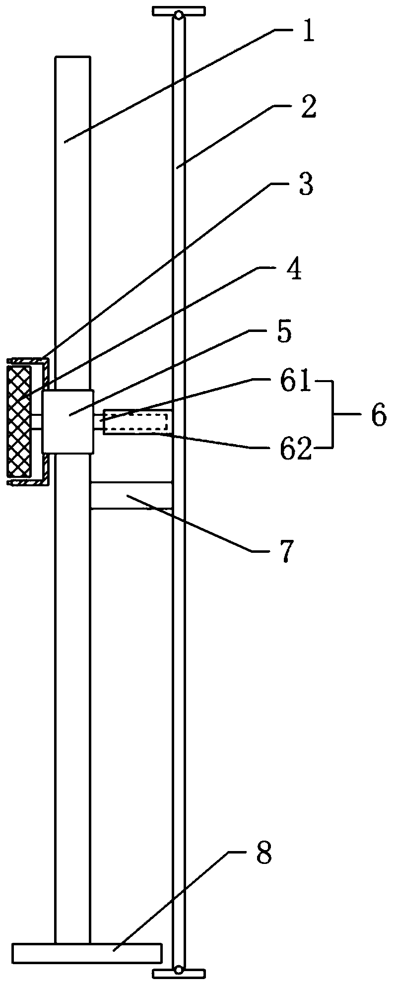
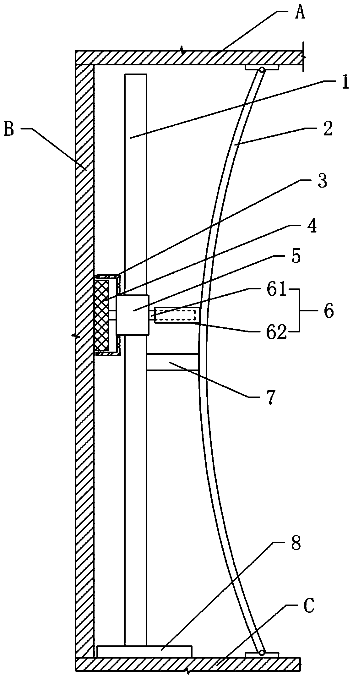
[0020] Embodiment one: as attached figure 1 Shown: the grinding device for architectural decoration, including a bracket, the bracket includes a base 8 and a vertical guide rod 1, the guide rod 1 is slidably connected with the base 8 in the horizontal direction, and the bottom of the base 8 is equipped with a walking wheel. In this embodiment, the walking wheel Preferably it is a universal wheel. The right side of the guide rod 1 is provided with a vertical elastic plate 2 , and a connecting rod 7 is welded between the middle part of the elastic plate 2 and the middle part of the guide rod 1 . The upper end of the elastic plate 2 is hinged with an upper top block that can be pressed against the ceiling A, and its lower end is hinged with a lower top block that can be pressed against the floor C. The side of the elastic plate 2 facing the guide bar 1 is vertically provided with a slide groove.

[0021] Slide block 5 is vertically slidably connected on guide bar 1, and slide b...

Embodiment 2

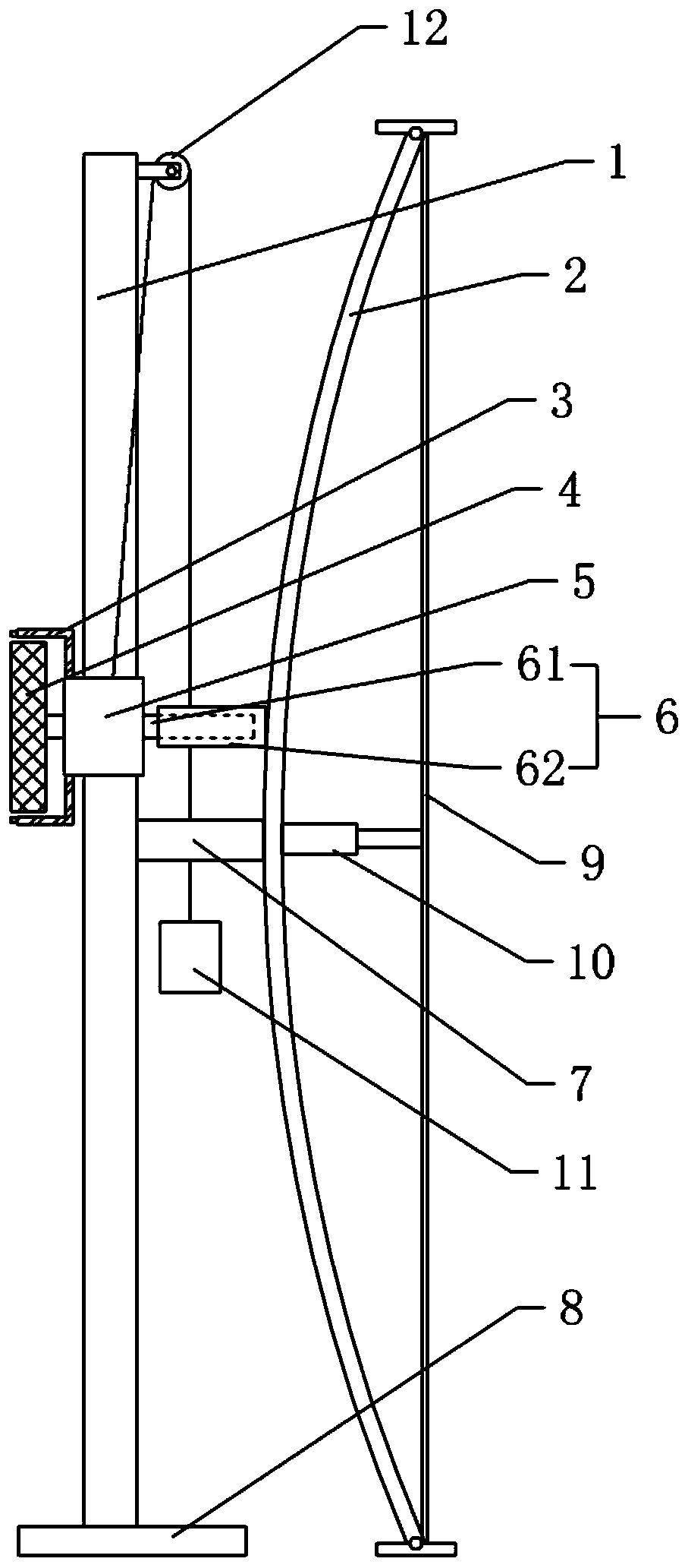
[0023] Embodiment two: the difference with embodiment one is only: as image 3 As shown, the upper end of the guide rod 1 is rotated with a fixed pulley 12, the fixed pulley 12 is wound with a traction rope, one end of the traction rope is connected with the slider 5, and the other end of the traction rope is connected with a counterweight 11; A stay rope 9 is connected between the upper and lower ends of the upper and lower ends; a telescopic adjustment mechanism 10 is connected between the stay rope 9 and the middle part of the elastic plate 2. In the present embodiment, the telescopic adjustment mechanism 10 is preferably a jack mechanism, and one end of the jack is connected with the bolt by a bolt. The middle part of elastic plate 2 is connected and fixed, and the other end of the jack is connected with the middle part of stay cord 9 . The weight of counterweight 11 is slightly less than the sum of the weights of all mechanisms installed on the slide block 5, utilize the ...


PUM


Abstract

The invention relates to the technical field of grinding equipment for building decoration, in particular to a grinding device for building decoration. The grinding device comprises a support. The support comprises a vertical guide rod. A sliding block is in sliding connection to the guide rod in the vertical direction. A grinding mechanism is arranged on the sliding block and comprises a grindingdisc and a drive mechanism driving the grinding disc to rotate. A vertical elastic plate is arranged on the support. Ejector blocks are hinged to the upper end and the lower end of the elastic plate,and the middle of the elastic plate is fixedly connected with the guide rod. A telescopic rod perpendicular to the guide rod is arranged between the sliding block and the elastic plate. The telescopic rod comprises a first telescopic segment and a second telescopic segment, the first telescopic segment and the second telescopic segment are in coaxial threaded connection, the first telescopic segment is rotationally connected with the sliding block and meanwhile is coaxially and fixedly connected with the grinding disc, and the second telescopic segment and the elastic plate are in sliding fit. By means of the scheme, the problem that a grinding device cannot be fixed by itself during use in the prior art is solved, and the manual cost of use is reduced.

Description

technical field [0001] The invention relates to the technical field of architectural decoration polishing equipment, in particular to a polishing device for architectural decoration. Background technique [0002] Grinding device is equipment commonly used in building decoration, and existing grinding device is generally all hand-held grinding devices, and when indoor wall surface is polished, it is necessary to set up a supporting platform to polish the upper part of wall surface. In order to reduce the risk of people standing at a high place for grinding, there is a device in the prior art that uses a bracket to support the grinding mechanism to grind the upper part of the wall. When this kind of grinding device is grinding, because the grinding device will be subjected to the force from the wall when grinding the wall surface, the grinding device has a tendency to move away from the wall surface, so the worker needs to hold the grinding device during the grinding process. ...

Claims


Application Information

Patent Timeline
Patent Type & Authority Applications(China)
IPC IPC(8): B24B7/18B24B41/02B24B41/04B24B41/00B24B47/12B24B55/04B24B55/06
CPCB24B7/182B24B7/186B24B41/00B24B41/02B24B41/04B24B47/12B24B55/04B24B55/06
Inventor 邹松夏
Owner CHONGQING VOCATIONAL INST OF ENG
Why Eureka
Try Eureka