
Fan tower tube connecting structure and construction method thereof

A technology for connecting structures and wind towers, which is applied in wind turbines, assembly of wind turbines, installation/support configuration of wind turbines, etc. It can solve problems such as breakage, safety accidents, and inability to obtain strong bending resistance at flange connections. , to achieve the effect of improving bending resistance, improving installation efficiency and improving convenience

Pending Publication Date: 2020-06-19
颜志成
View PDF0 Cites 0 Cited by
  • Summary
  • Abstract
  • Description
  • Claims
  • Application Information

AI Technical Summary

Problems solved by technology

[0003] The multi-section towers of the fan usually need to be connected by flanges. The common method in the prior art is to install flanges at the ends of the adjacent towers, and then pass the flanges at the two ends through the fixing parts. However, in practical applications, the place where the fan is installed usually has a strong wind force, and the flange connection cannot obtain strong bending resistance through the above-mentioned simple connection, and it is very likely to break under the action of strong wind, and even cause a safety accident

Method used


Image

  • Fan tower tube connecting structure and construction method thereof
  • Fan tower tube connecting structure and construction method thereof
  • Fan tower tube connecting structure and construction method thereof

Examples


Embodiment Construction

[0053] Reference will now be made in detail to the exemplary embodiments, examples of which are illustrated in the accompanying drawings. When the following description refers to the accompanying drawings, the same numerals in different drawings refer to the same or similar elements unless otherwise indicated. The implementations described in the following exemplary examples do not represent all implementations consistent with the present invention. Rather, they are merely examples of apparatuses and methods consistent with aspects of the invention as recited in the appended claims.

[0054] The terminology used in the present invention is for the purpose of describing particular embodiments only and is not intended to limit the invention. As used herein and in the appended claims, the singular forms "a", "the", and "the" are intended to include the plural forms as well, unless the context clearly dictates otherwise. It should also be understood that the term "and / or" as use...


PUM


Abstract

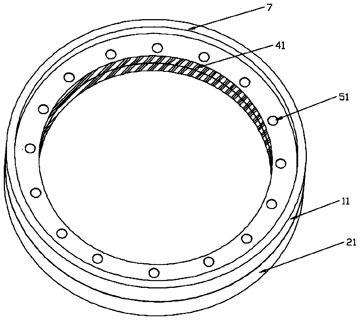
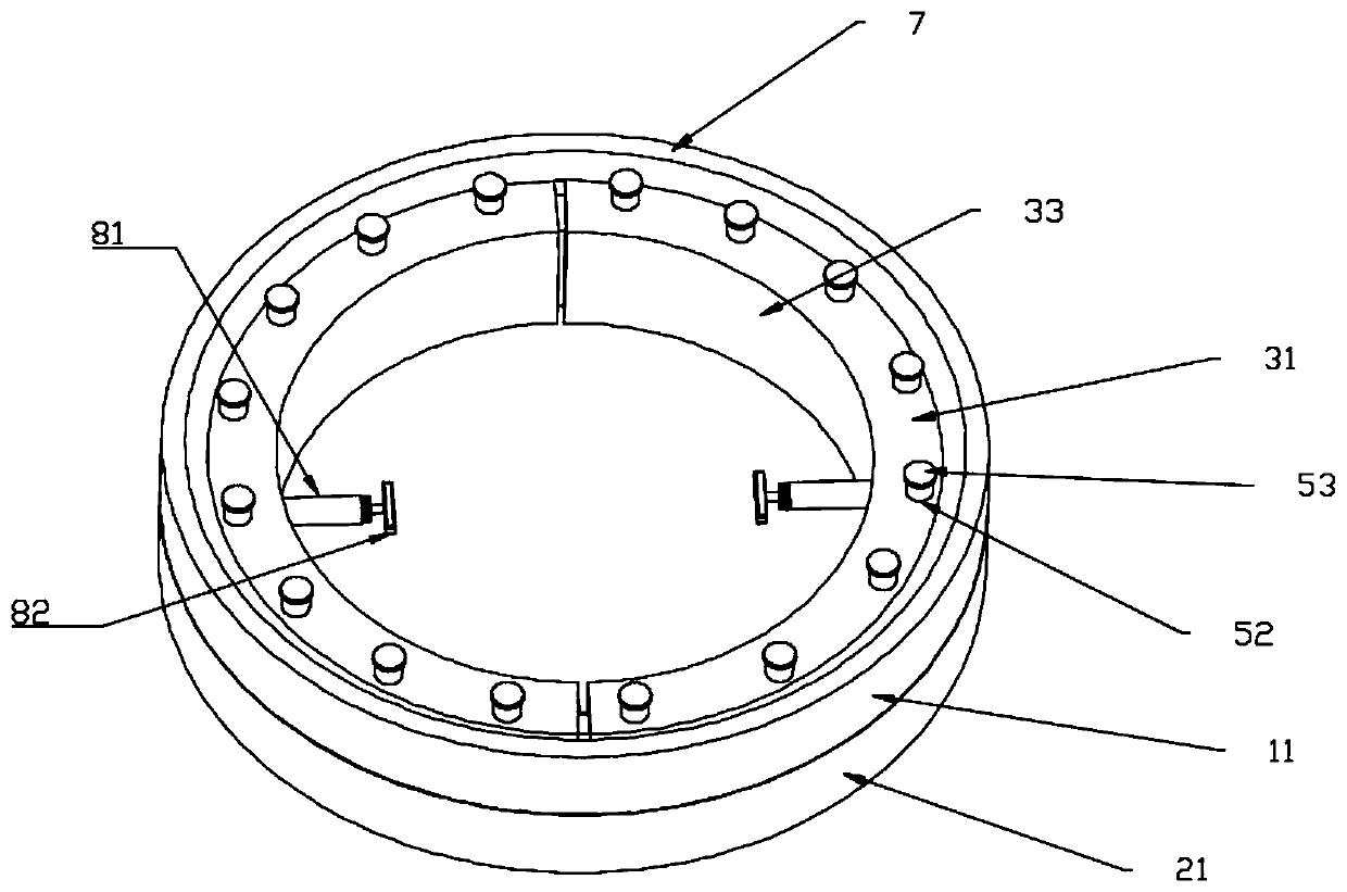
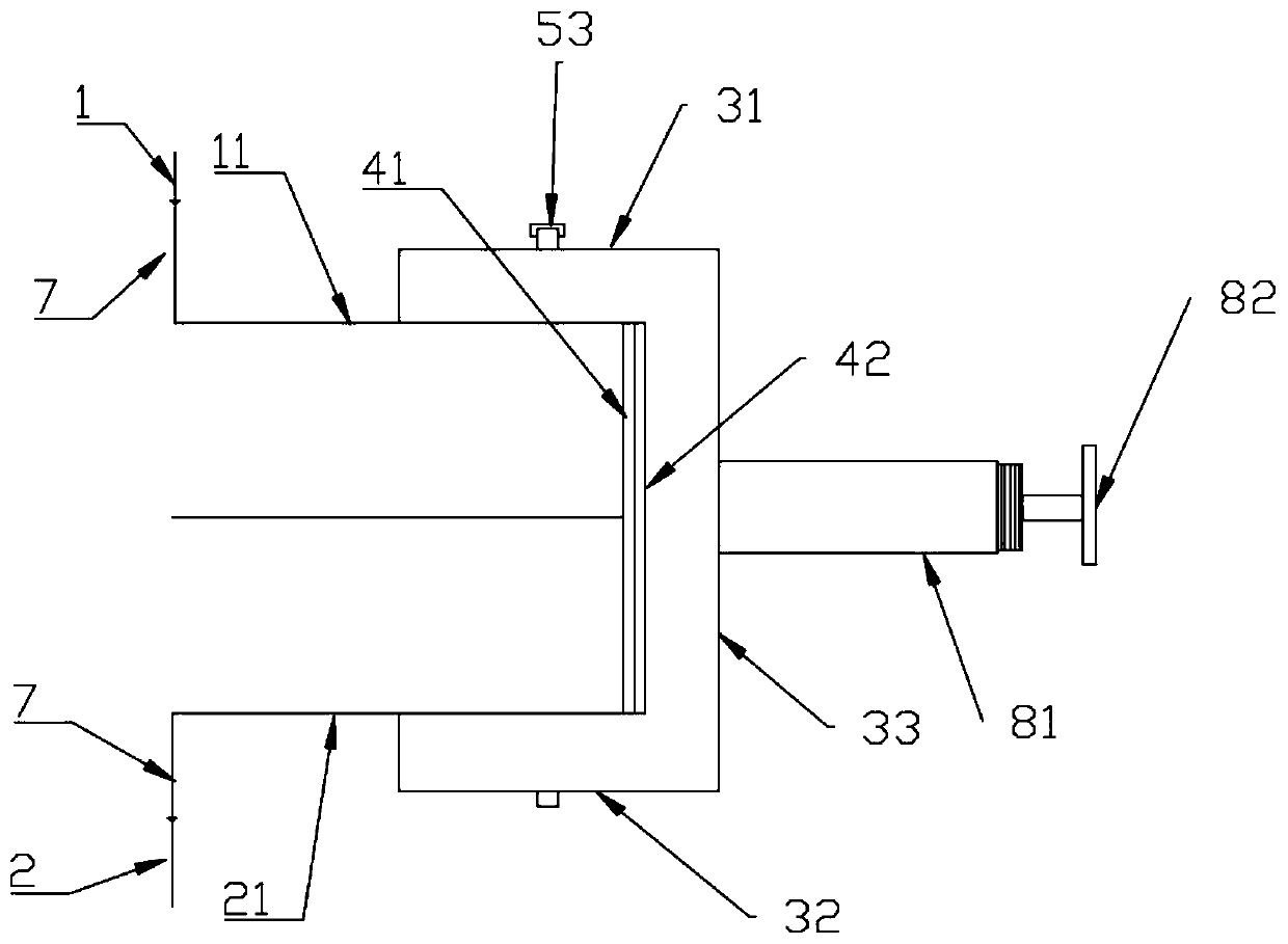
The invention relates to the technical field of wind power generation, in particular to a fan tower tube connecting structure and a construction method thereof. The fan tower tube connecting structurecomprises an upper tower tube, a lower tower tube connected with the upper tower tube, and a clamping device; an upper flange is arranged at the junction of the upper tower tube and the lower tower tube, and the lower tower tube is provided with a lower flange connected with the upper flange at the junction; the clamping device can tighten the upper flange and the lower flange together; and the upper flange and / or the lower flange is provided with a first magnetic attraction part, and the clamping device is provided with a second magnetic attraction part connected with the first magnetic attraction part. Through arrangement of the clamping device, the technical problem that the strength of the junction of the upper fan tower tube and the lower fan tower tube is insufficient is solved, andthe strength of the junction is improved; and through cooperative arrangement of the first magnetic attraction part and the second magnetic attraction part, the technical problems that the strength of the junction of the upper fan tower tube and the lower fan tower tube is insufficient and the clamping device is not prone to being aligned at the upper flange and the lower flange during mounting are further effectively solved, and the strength of the junction is effectively improved.

Description

Technical field: [0001] The invention relates to the technical field of wind power generation, in particular to a fan tower connection structure and a construction method. Background technique: [0002] Wind generators, referred to as fans, are power equipment that convert wind energy into mechanical work, which drives the rotor to rotate, and finally outputs alternating current. Fans are installed on land and at sea; the main support structure of the fan is the tower, and the tower of the fan The tube is usually divided into multiple sections, which need to be connected, including the connection between the tower tube and the foundation, and between the sections of the tower tube. [0003] The multi-section towers of the fan usually need to be connected by flanges. The common method in the prior art is to install flanges at the ends of the adjacent towers, and then pass the flanges at the two ends through the fixing parts. However, in practical applications, the place wher...

Claims


Application Information

Patent Timeline
IPC IPC(8): F03D13/20F03D80/00F03D80/50F03D13/10
CPCF03D13/10F03D13/20F03D13/22F03D80/00F03D80/50Y02E10/72Y02E10/728
Inventor 颜志成纪延涛刘倩霍晓刚李铭孙铭艺赵文明
Owner 颜志成
Learn More