Soil shear strength testing equipment and testing method

A technology of shear strength and testing equipment, which is applied in the direction of applying stable shear force to test material strength, strength characteristics, measuring devices, etc., which can solve the lack of accurate judgment and measurement data that affect surveyors on the stability of soil layers Insufficient precision and other problems, to achieve the effect of improving accuracy

Inactive Publication Date: 2020-06-19
上海金地工程勘察有限公司
View PDF7 Cites 4 Cited by
  • Summary
  • Abstract
  • Description
  • Claims
  • Application Information

AI Technical Summary

Problems solved by technology

[0004] The above-mentioned existing technical solutions have the following defects: the surveyors measure the shear force on the soil through the deformation of the force-measuring ring, and the equipment lacks equipment for accurately measuring the variable of the force-measuring ring. At the same time, the force-measuring ring changes easily with the The pulleys on the seco

Method used


Image

  • Soil shear strength testing equipment and testing method
  • Soil shear strength testing equipment and testing method
  • Soil shear strength testing equipment and testing method

Examples


Embodiment 1

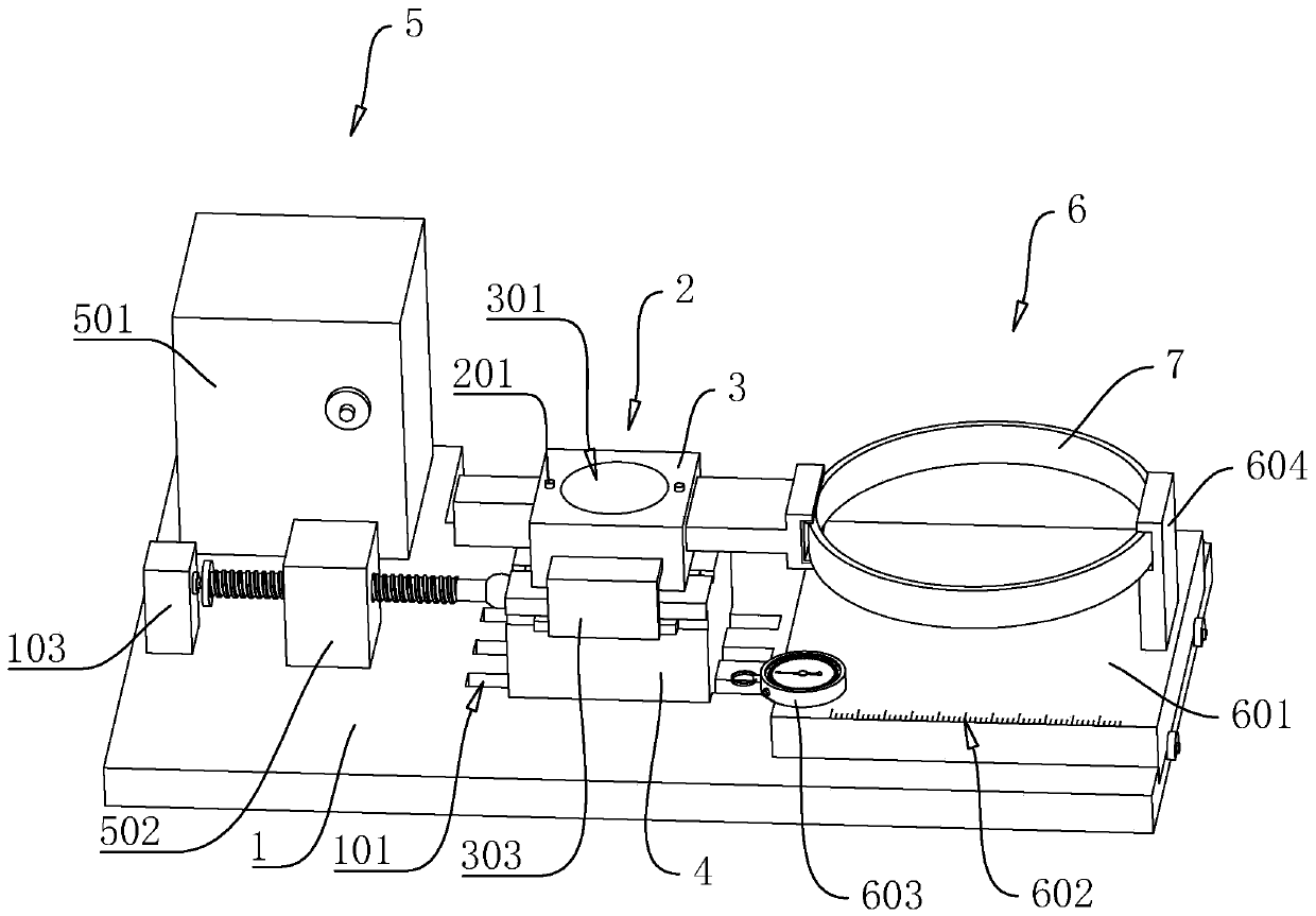
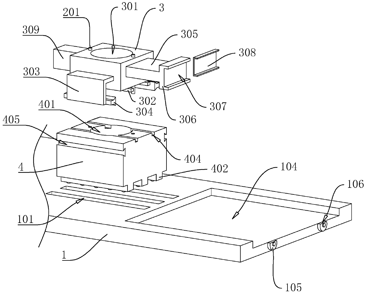
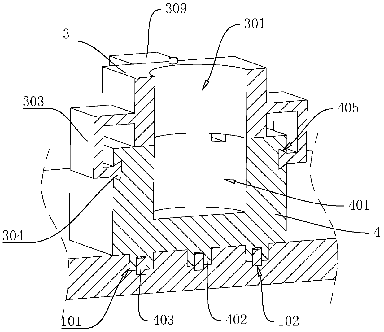
[0042] A kind of soil shear strength test equipment, with reference to figure 1 , figure 2 and image 3 , including a bottom plate 1 and a shear box 2 located on the bottom plate 1 . The shearing box 2 includes a lower box 4 and an upper box 3 slidably arranged on the lower box 4, and a positioning pin 201 is arranged between the upper box 3 and the lower box 4 to limit the relative slippage between the two. The upper surface of the upper box 3 is provided with a first through hole 301 along its own thickness direction, and the upper surface of the lower box 4 is provided with a second through hole 401. The first through hole 301 and the second through hole 401 are jointly used to place the The soil is agglomerated, and the inner bottom wall of the second through hole 401 is used to bear the soil agglomerates.

[0043] refer to figure 2 and image 3 , the upper surface of the bottom plate 1 is provided with a plurality of sliding grooves 101, and the bottom wall of the ...

Embodiment 2

[0056] A test method for soil shear strength testing equipment, comprising the following steps:

[0057] Sample preparation: first cut the undisturbed soil into rectangular agglomerates with a flat outer surface with a ring knife. When cutting the undisturbed soil, ensure that the solid-liquid-gas three-state balance of the undisturbed soil is cut, that is, the undisturbed soil is not sticky or loose after cutting. After standing for 20 minutes, it still maintains a specific shape; then use a cylinder with a sharp bottom to open a mold on the rectangular agglomerate to obtain a cylindrical sample.

[0058] Debugging the sample: pass the cylindrical sample through the first through hole 301 and into the second through hole 401, and adjust its position so that the position of the cylindrical sample in the shear box 2 tends to be stable.


PUM


Abstract

The invention discloses soil shear strength testing equipment and a testing method, and relates to the technical field of soil shear strength testing equipment. The technical problem that a common direct shear apparatus is inaccurate in measurement of shear force borne by soil is solved. According to the technical scheme, the device is characterized by comprising a bottom plate and a shearing boxlocated on the bottom plate; the shearing box comprises a lower box body and an upper box body arranged on the lower box body in a sliding mode. A driving device and a force measuring device are respectively arranged at two ends of the upper surface of the bottom plate in the length direction of the shearing box; the force measuring device comprises a supporting plate, an abutting block and a force measuring ring, an extending strip is vertically arranged on the outer side wall of the upper box and faces the side wall of the force measuring ring, a connecting block is arranged at the end, awayfrom the upper box, of the extending strip, and an abutting groove is formed in the side wall, away from the extending strip, of the connecting block; scale marks are arranged on the upper surface ofthe supporting plate in the length direction of the supporting plate, a stopwatch is arranged on the upper surface of the supporting plate, and the effect of effectively improving the accuracy of thesoil direct shear apparatus for measuring the soil shear strength is achieved.

Description

technical field [0001] The invention relates to the technical field of soil shear strength testing equipment, more specifically, it relates to a soil shear strength testing equipment and a testing method. Background technique [0002] At present, the stability of the soil layer mainly depends on the shear strength of the soil itself. When the shear stress in the soil cake exceeds its own shear strength, the soil cake will slide along any part of its surface or inside. The surface slides, and the whole piece of soil agglomerates and falls apart, which can easily cause slope landslides and the phenomenon that the cultivated layer is difficult to support the cultivation of crops. Soil direct shear instrument is a kind of soil shear strength testing equipment, which can more accurately detect the shear strength that the soil can withstand, and then allow surveyors to evaluate the stability of the soil layer where the soil is located. [0003] Existing application number is that...

Claims


Application Information

Patent Timeline
IPC IPC(8): G01N3/24G01N3/02
CPCG01N3/24G01N3/02
Inventor 于波刘建泰
Owner 上海金地工程勘察有限公司
Why Eureka
Try Eureka