Dynamic inversion method and system for power system fault diagnosis
A technology of fault diagnosis and power system, which is applied in fault location, fault detection according to conductor type, measurement of electricity and other directions, and can solve problems such as abnormal operation status and faults
- Summary
- Abstract
- Description
- Claims
- Application Information
AI Technical Summary
Problems solved by technology
Method used
Image
Examples
Embodiment 1
[0026] The fault recording method is a fault diagnosis method for dispatching power grid based on fault recording information. The fault recorder is used in the power system. When the system fails, it can automatically and accurately record the changes of various electrical quantities in the process before and after the fault. Through the analysis and comparison of these electrical quantities, it can analyze and handle accidents and judge protection. It plays an important role in correct operation and improving the safe operation level of power system.
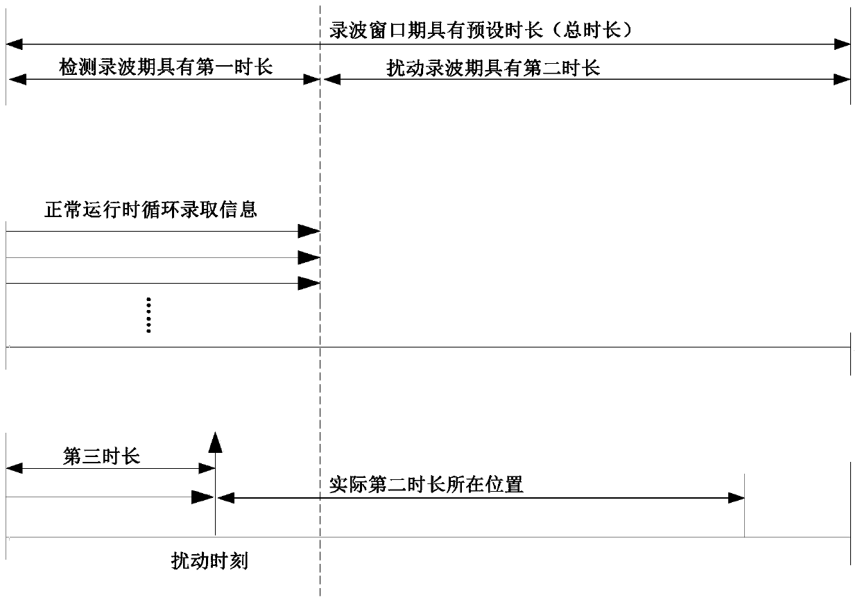
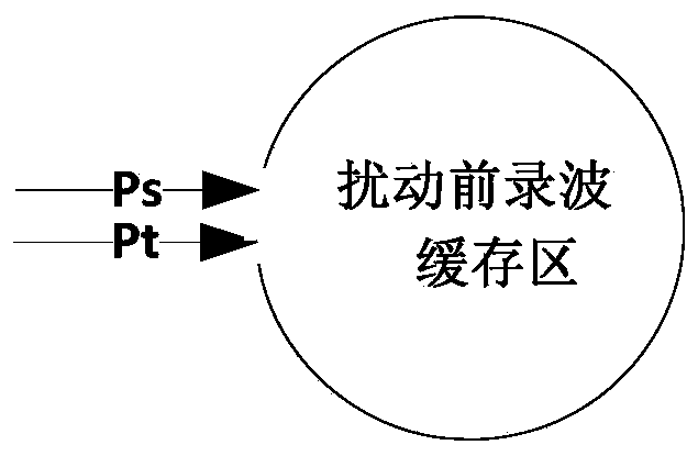
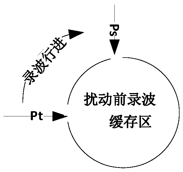
[0027] The embodiment of the present invention provides an information recording method for expert diagnosis of power system faults, please refer to Figure 1 to Figure 8 .
[0028] Please refer to figure 1 , the method includes:
[0029] Define the wave recording window period, the wave recording window period includes the detection wave recording period of wave recording before the disturbance event occurs, and the distur...
Embodiment 2
[0063] Another embodiment of the present invention provides another information recording method for expert diagnosis of power system faults, please refer to Figure 9 , the method includes:
[0064] Define the wave recording window period, the wave recording window period includes the detection wave recording period of wave recording before the disturbance event occurs, and the disturbance wave recording period of wave recording after the disturbance event occurs;
[0065] The recording window period has a preset duration; a complete period of the detection recording period has a first duration;
[0066] Using the detection recording period to perform dynamic ring recording detection, if no disturbance event is detected in one detection recording period, then enter the next detection recording period;
[0067] During one described detection recording period, if a disturbance event is detected when passing through the second duration, record the disturbance event and the time...
Embodiment 3
[0082] An embodiment of the present invention provides a dynamic inversion method for power system fault diagnosis, including:
[0083] The wave recording step defines the wave recording window period, and the wave recording window period includes the detection wave recording period for wave recording before the disturbance event occurs, and the disturbance wave record period for wave recording after the disturbance event occurs;
[0084] Using the recording window period to record the data information of the detection recording period and the data information of the disturbance recording period;
[0085] Diagnosing and recording steps, after the disturbance event subsides, start the expert diagnosis of the disturbance event, and record the diagnostic reasoning process;
[0086] The graphical dynamic display step is to graphically invert the diagnostic reasoning process according to the time sequence of the occurrence of the disturbance event, and display the expert rules trav...
PUM
 Abstract
Description
Claims
Application Information
 - R&D
- Intellectual Property
- Life Sciences
- Materials
- Tech Scout
- Unparalleled Data Quality
- Higher Quality Content
- 60% Fewer Hallucinations
Browse by: Latest US Patents, China's latest patents, Technical Efficacy Thesaurus, Application Domain, Technology Topic, Popular Technical Reports.
© 2025 PatSnap. All rights reserved.Legal|Privacy policy|Modern Slavery Act Transparency Statement|Sitemap|About US| Contact US: help@patsnap.com


