Projection device for changing imaging effect through light refraction

A technology of projection equipment and image effects, which is applied in the direction of optics, instruments, projection devices, etc., can solve the problems of cumbersome, limited range of use of projectors, troubles, etc.

Inactive Publication Date: 2020-06-19
杭州新五板全息科技有限公司
View PDF9 Cites 3 Cited by
  • Summary
  • Abstract
  • Description
  • Claims
  • Application Information

AI Technical Summary

Problems solved by technology

[0003] Due to the fixed lens size of traditional optical instruments, the projected video area is mostly fixed size. If the user wants to expand the video area in some larger spaces, a professional must disassemble the case and adjust the distance between the focal length and the lens. The distance is cumbersome and cumbersome, which limits the scope of use of the projector; in addition, the light source of the projection device will emit a lot of heat energy during the projection process, and the heat energy will accumulate near the lens, causing the lens to refract light and bear heat while intensifying Its own temperature will cause the aging of the lens and reduce the effect of the projected picture. Therefore, a projection device that uses light refraction to change the image effect came into being.

Method used


Image

  • Projection device for changing imaging effect through light refraction
  • Projection device for changing imaging effect through light refraction
  • Projection device for changing imaging effect through light refraction

Examples


Embodiment Construction

[0024] The following will clearly and completely describe the technical solutions in the embodiments of the present invention with reference to the accompanying drawings in the embodiments of the present invention. Obviously, the described embodiments are only some, not all, embodiments of the present invention. Based on the embodiments of the present invention, all other embodiments obtained by persons of ordinary skill in the art without making creative efforts belong to the protection scope of the present invention.

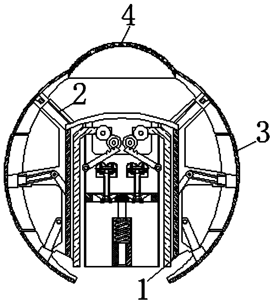
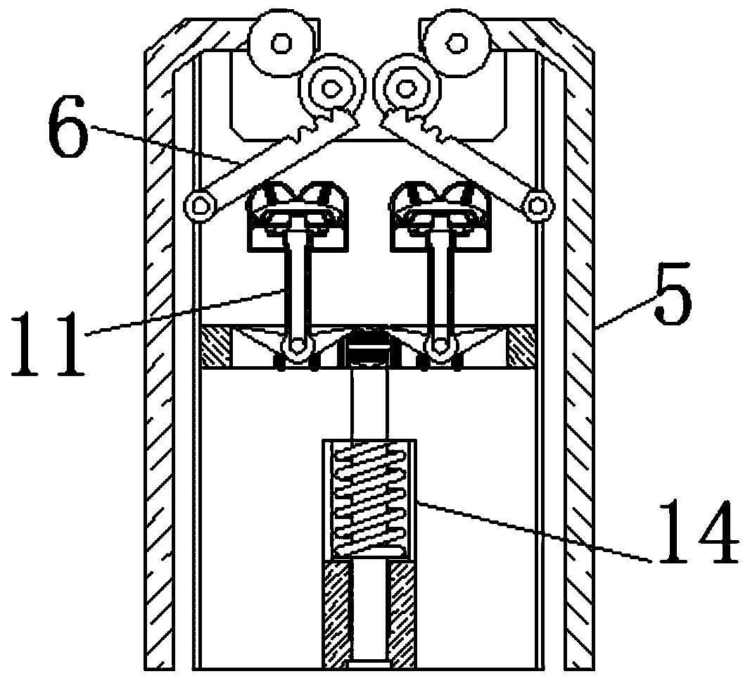
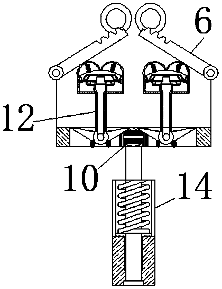
[0025] see Figure 1-8 , a projection device that uses light refraction to change the image effect, including a housing 1, the surface of the housing 1 is movably connected with a telescopic rod 2, the telescopic rod 2 plays the role of pushing and pulling the folding mirror 3, and the surface of the telescopic rod 2 is movably connected There is a folding mirror 3, and the surface of the folding mirror 3 is fixedly connected with a flexible screen 4. The fold...


PUM


Abstract

The invention relates to the technical field of projection equipment. The invention further discloses a projection device for changing the imaging effect through light refraction. The device comprisesa shell, a telescopic rod is movably connected to the surface of the shell, a folding mirror is movably connected to the surface of the telescopic rod, a flexible screen is fixedly connected to the surface of the folding mirror, a toothed plate is movably connected to the interior of the shell, an extrusion plate is movably connected to the surface of the toothed plate, an elastic cover is movably connected to the surface of the extrusion plate, and a compression spring is movably connected to the interior of the elastic cover. If the range of the video projected at the moment is too small, the extrusion plate can be pushed to move towards two sides, and the extrusion plate meshes the toothed plate to push the shell to rotate away, and drives the folding mirror to rotate to the state shown in the figure 8. When the folding mirror is unfolded, the spring rod pushes the lamp source to move in the direction close to the folding mirror. In the moving process, it is known that the maximumprojection picture is enlarged from the maximum projection picture, and therefore the effect of changing the shape of the convex lens and the focal length to enlarge the projection picture is achieved.

Description

technical field [0001] The invention relates to the technical field of projection equipment, in particular to a projection equipment that uses light refraction to change the image rendering effect. Background technique [0002] A projector is an optical instrument that uses optical elements to enlarge the outline of a workpiece and projects it onto a video screen. It is popular for its portability and good visual effects; , light sources, circuits, etc., in which the optical system includes glass lenses such as convex lenses and flat mirrors, which are the key to projection molding. [0003] Due to the fixed lens size of traditional optical instruments, the projected video area is mostly fixed size. If the user wants to expand the video area in some larger spaces, a professional must disassemble the case and adjust the distance between the focal length and the lens. The distance is cumbersome and cumbersome, which limits the scope of use of the projector; in addition, the l...

Claims


Application Information

Patent Timeline
Patent Type & Authority Applications(China)
IPC IPC(8): G03B21/14G03B21/16G03B21/20
CPCG03B21/142G03B21/16G03B21/20G03B21/2013
Inventor 王铜森
Owner 杭州新五板全息科技有限公司
Why Eureka
Try Eureka