A Torque Ripple Suppression Method of Switched Reluctance Motor

A switched reluctance motor and torque pulsation technology, which is applied in the direction of AC motor control, motor vibration suppression control, control system, etc., can solve problems such as limiting the application of switched reluctance motors, power factor drop, and instantaneous torque pulsation. Achieve the effect of realizing the power factor correction function, reducing the current change rate, and ensuring stability

Active Publication Date: 2021-12-14
BENGBU COLLEGE
View PDF5 Cites 0 Cited by
  • Summary
  • Abstract
  • Description
  • Claims
  • Application Information

AI Technical Summary

Problems solved by technology

[0002] The switched reluctance motor (SRM) has a unique double salient pole structure. The operation of the switched reluctance motor follows the "minimum reluctance principle". By cyclically applying excitation to the power converter of each phase, the rotor continues to In recent years, due to its simple structure, large starting torque, low manufacturing cost, wide speed range, high reliability and efficiency, switched reluctance motors have been widely used in mining machinery, oil field pumping units, wind power generation, electric vehicles, etc. However, the double salient pole structure and torque-current-angle non-linear magnetic characteristics of switched reluctance motors lead to obvious instantaneous torque ripples, especially at low speeds and during commutation The torque ripple will directly cause the speed fluctuation, which greatly limits the application of switched reluctance motors in high-performance occasions. Therefore, how to effectively and economically suppress the torque ripple of switched reluctance motors has an important academic value and engineering application value
[0003] The topology of the power converter of the traditional switched reluctance motor speed control system includes large filter capacitors and rectifier diodes. The power frequency AC power supply obtains the DC bus voltage through bridge rectification and capacitor filtering. , the voltage change at both ends of the capacitor must be very small, so the capacity of the filter capacitor is relatively large. When the power converter performs AC / DC conversion, due to the charging and discharging of the filter capacitor, the DC voltage will appear in the shape of a sawtooth wave. The minimum value of the voltage is not zero and there is not much difference from its maximum value. According to the unidirectional conductivity of the bridge rectifier diode, only when the instantaneous value of the AC input voltage is lower than the voltage on the filter capacitor, the rectifier diode is reverse biased And cut-off; that is to say, in every half cycle of the AC line voltage, the diode will conduct only near its peak value (the conduction angle is about 70°). Although the AC input voltage still maintains a sinusoidal waveform, the AC The input current is a high-amplitude peak pulse. This severely distorted current waveform contains a large number of harmonic components, which causes a serious drop in power factor. From the perspective of energy saving, it is very important to increase the power and maintain the sinusoidal input current;

Method used


Image

  • A Torque Ripple Suppression Method of Switched Reluctance Motor
  • A Torque Ripple Suppression Method of Switched Reluctance Motor
  • A Torque Ripple Suppression Method of Switched Reluctance Motor

Examples


Embodiment Construction

[0026] The following will clearly and completely describe the technical solutions in the embodiments of the present invention with reference to the accompanying drawings in the embodiments of the present invention. Obviously, the described embodiments are only some, not all, embodiments of the present invention. Based on the embodiments of the present invention, all other embodiments obtained by persons of ordinary skill in the art without making creative efforts belong to the protection scope of the present invention.

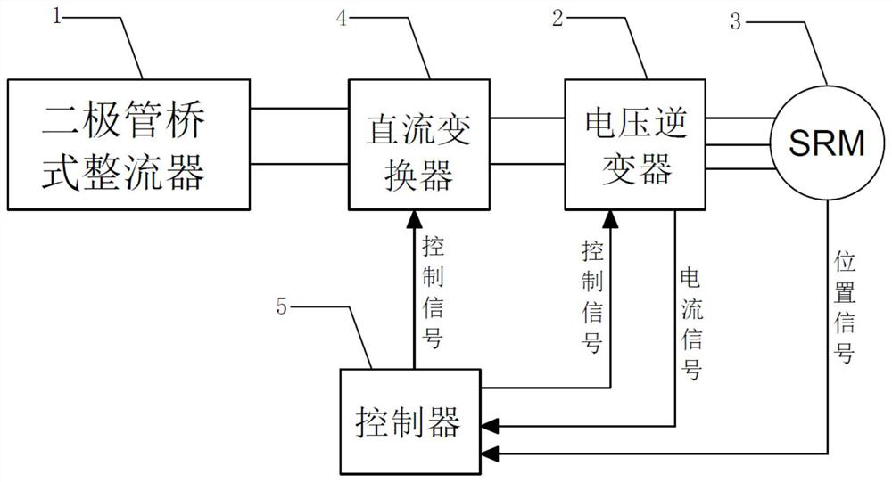
[0027] see Figure 1-5 , the present invention provides a technical solution:

[0028] A method for suppressing torque ripple of a switched reluctance motor, comprising a diode bridge rectifier 1, a voltage inverter 2, and a switched reluctance motor 3, wherein the diode bridge rectifier 1, the voltage inverter 2, and the switched reluctance motor 3 are arranged in series A DC converter 4 is added between the rear end of the diode bridge rectifier 1 and the f...


PUM


Abstract

The invention discloses a method for suppressing torque ripple of a switched reluctance motor, which comprises a diode bridge rectifier, a voltage inverter and a switched reluctance motor, wherein the diode bridge rectifier, the voltage inverter and the switched reluctance motor are arranged in series A DC converter is added between the rear end of the diode bridge rectifier and the front end of the voltage inverter, and the voltage inverter, DC converter and switched reluctance motor are all electrically connected to the controller; The controller is used to monitor the rotating speed and phase current of the switched reluctance motor and the output voltage and output current of the DC converter; the present invention adds a DC voltage regulating circuit between the diode rectifier circuit and the voltage inverter circuit, and speeds up the phase change in the commutation stage. The commutation speed and the non-commutation stage reduce the current change rate, and at the same time, by controlling the input current waveform, the power factor correction function is realized, the torque ripple is effectively suppressed, and the stability of the speed is guaranteed.

Description

technical field [0001] The invention relates to the technical field of motor control, in particular to a method for suppressing torque ripple of a switched reluctance motor. Background technique [0002] The switched reluctance motor (SRM) has a unique double salient pole structure. The operation of the switched reluctance motor follows the "minimum reluctance principle". By cyclically applying excitation to the power converter of each phase, the rotor continues to In recent years, due to its simple structure, large starting torque, low manufacturing cost, wide speed range, high reliability and efficiency, switched reluctance motors have been widely used in mining machinery, oil field pumping units, wind power generation, electric vehicles, etc. However, the double salient pole structure and torque-current-angle non-linear magnetic characteristics of switched reluctance motors lead to obvious instantaneous torque ripples, especially at low speeds and during commutation The ...

Claims


Application Information

Patent Timeline
Patent Type & Authority Patents(China)
IPC IPC(8): H02P25/098H02P23/04H02P23/26
CPCH02P25/098H02P23/04H02P23/26
Inventor 荆建立黄迎辉王强秦国威
Owner BENGBU COLLEGE
Why Eureka
Try Eureka