
Membrane gas separation under magnetic field

A gas separation and gas technology, applied in semi-permeable membrane separation, separation methods, gas treatment, etc., can solve problems such as insufficient membrane performance

Inactive Publication Date: 2020-06-19
KHALIFA UNIV OF SCI & TECH
View PDF14 Cites 0 Cited by
  • Summary
  • Abstract
  • Description
  • Claims
  • Application Information

AI Technical Summary

Problems solved by technology

[0013] Another object of the present invention is to provide devices, methods and uses that overcome, inter alia, current disadvantages of insufficient membrane performance caused by gas flow direction through membrane gaps instead of pores, pore orientation, membrane thickness, uniform pore morphology and function

Method used


Image

  • Membrane gas separation under magnetic field
  • Membrane gas separation under magnetic field
  • Membrane gas separation under magnetic field

Examples


Embodiment Construction

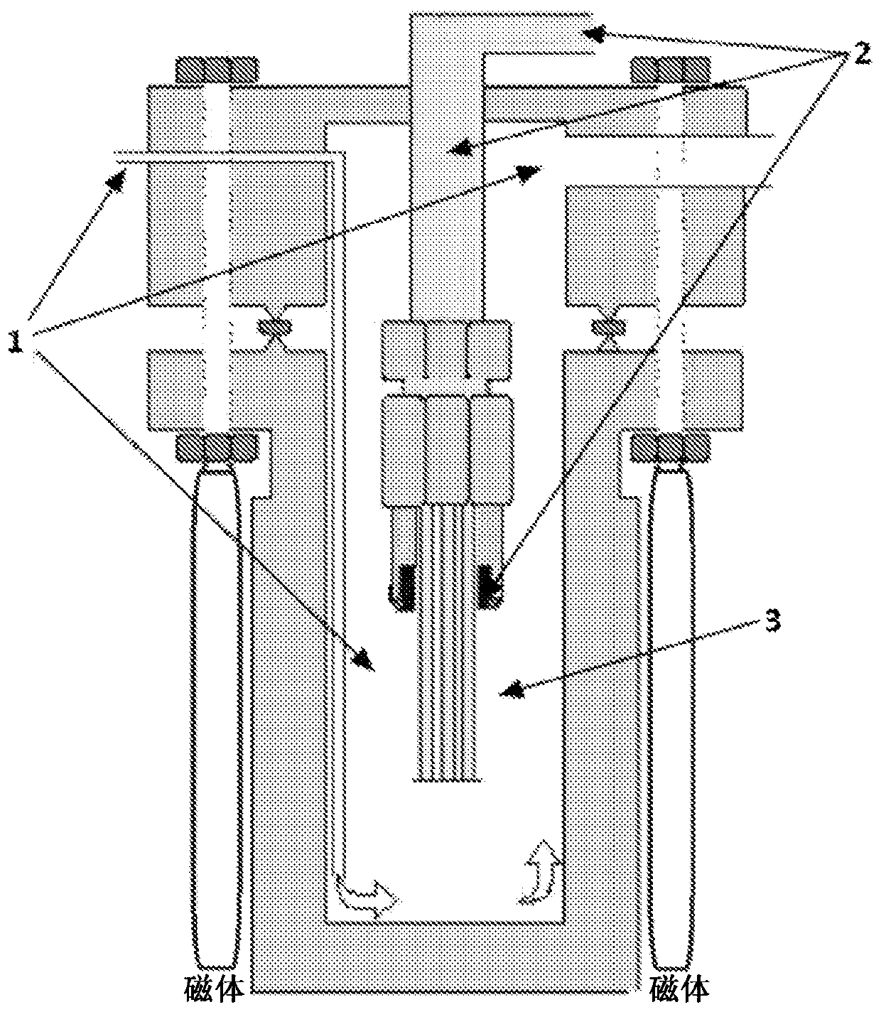
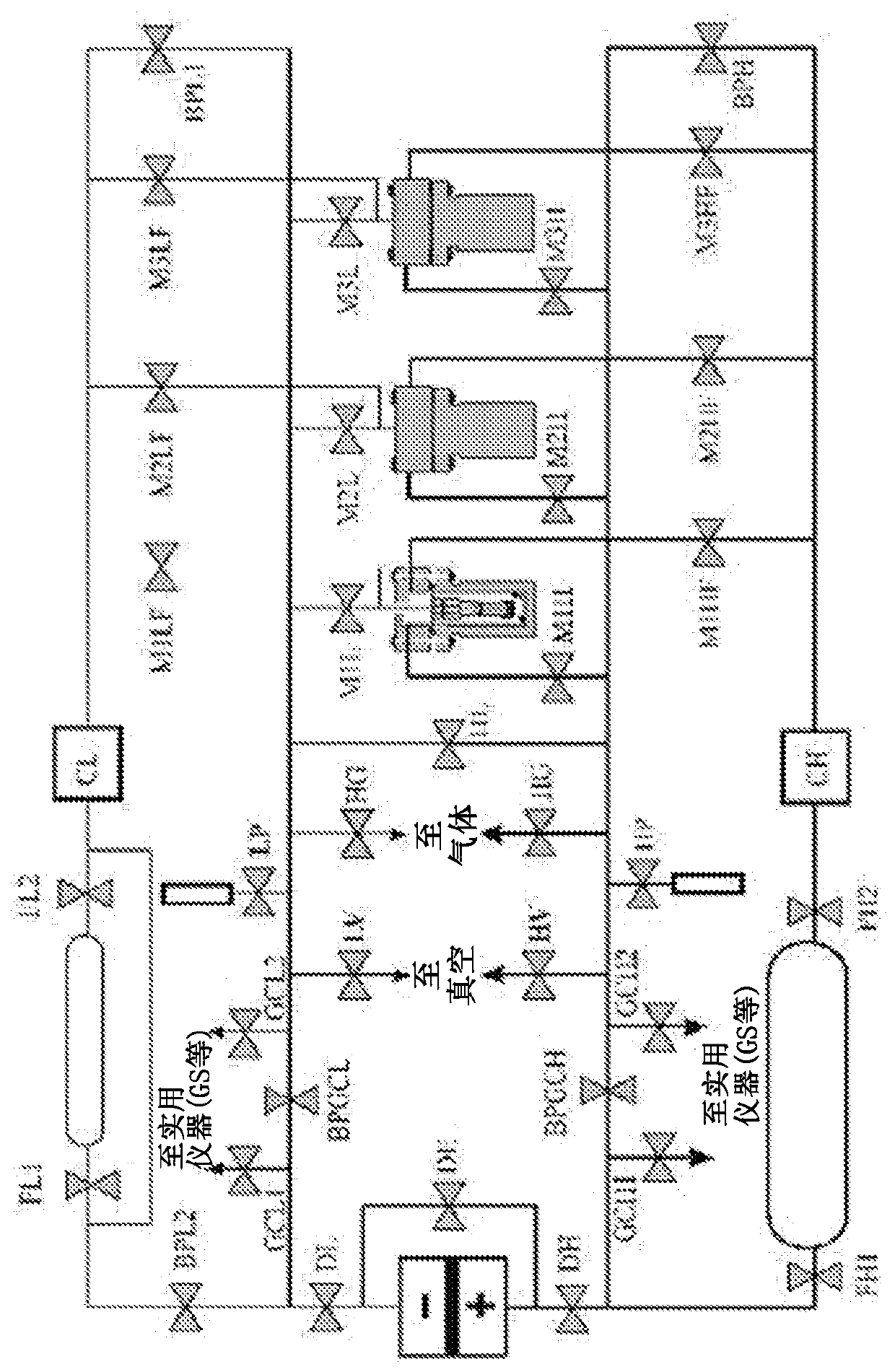
[0038] The invention provides, inter alia, a device for separating a gas mixture of at least two different gases,

[0039] wherein the device comprises a first chamber and a second chamber,

[0040] wherein the first chamber has at least one inlet for feeding the gas mixture into the first chamber,

[0041] wherein the first chamber has at least one outlet for recovering at least a portion of at least one of the at least two gases,

[0042] wherein the second chamber has at least one outlet for recovering at least a portion of the other of the at least two gases,

[0043] wherein the first chamber and the second chamber are in contact and separated by a membrane,

[0044] Wherein the membrane is surrounded by magnets. The magnet in particular enables an external magnetic field to be applied to or onto the membrane.

[0045] The device allows reliable and efficient separation of gas mixtures, in particular mixtures of at least two different gases. The membranes used increa...


PUM

PropertyMeasurementUnit
glass transition temperatureaaaaaaaaaa

Abstract

Apparatus, methods and uses for separating gas mixtures of at least two different gases under magnetic field and employing a membrane are described.

Description

technical field [0001] The invention relates to a device, a method and a use for separating a gas mixture of at least two different gases into its individual components under a magnetic field and by using a membrane. Background technique [0002] The sensitivity of certain gases to magnetic fields has been demonstrated long ago, however, so far, the application of this principle in membrane-based separations of various gas mixtures has not been thoroughly investigated. [0003] The repulsive or attractive forces induced by the magnetic field can act selectively on mixtures that exhibit high magnetic susceptibility, such as gases containing oxygen, nitrogen, or carbon dioxide. Faraday first reported in 1847 that bubbles of oxygen would be attracted to the center of a strong magnetic field (J. Tyndall, Faraday as discoverer, London: Longmans, Green, and Co., (1868) 108-119). About 100 years later, Pauling, Wood and Sturdivant developed a paramagnetic oxygen analyzer for deter...

Claims


Application Information

Patent Timeline
Patent Type & Authority Applications(China)
IPC IPC(8): B01D53/22B01D61/36
CPCB01D53/228B01D2256/12B01D2256/16B01D2256/18B01D2256/245B01D2257/304B01D2257/504B01D2259/814B01D63/02B01D71/021B01D71/64B01D2311/2607Y02C20/40B01D53/229B01D69/08B01D2053/224
Inventor 乔治斯·卡拉尼克劳斯埃万盖洛斯·P·法瓦斯尼古劳斯·S·埃利奥普洛斯塞尔焦·K·帕帕乔治乌
Owner KHALIFA UNIV OF SCI & TECH
Learn More