Steelmaking device and process for continuously preheating scrap steel

A scrap and process technology, which is applied in the field of steelmaking equipment for continuous preheating of scrap, can solve problems such as water leakage in shafts and finger valves, high scrap preheating temperature, and poor preheating effect.

Pending Publication Date: 2020-06-23
MCC CAPITAL ENGINEERING & RESEARCH
View PDF8 Cites 9 Cited by
  • Summary
  • Abstract
  • Description
  • Claims
  • Application Information

AI Technical Summary

Problems solved by technology

Among them, the Consteel electric furnace equipment has mature technology and low failure rate, but because the flue gas only passes through the top of the scrap steel, the preheating effect is poor, and the power consumption per ton of steel can save up to 30kWh
For shaft-type electric furnaces with finger valves, since the flue gas diffuse

Method used


Image

  • Steelmaking device and process for continuously preheating scrap steel

Examples


Embodiment 1

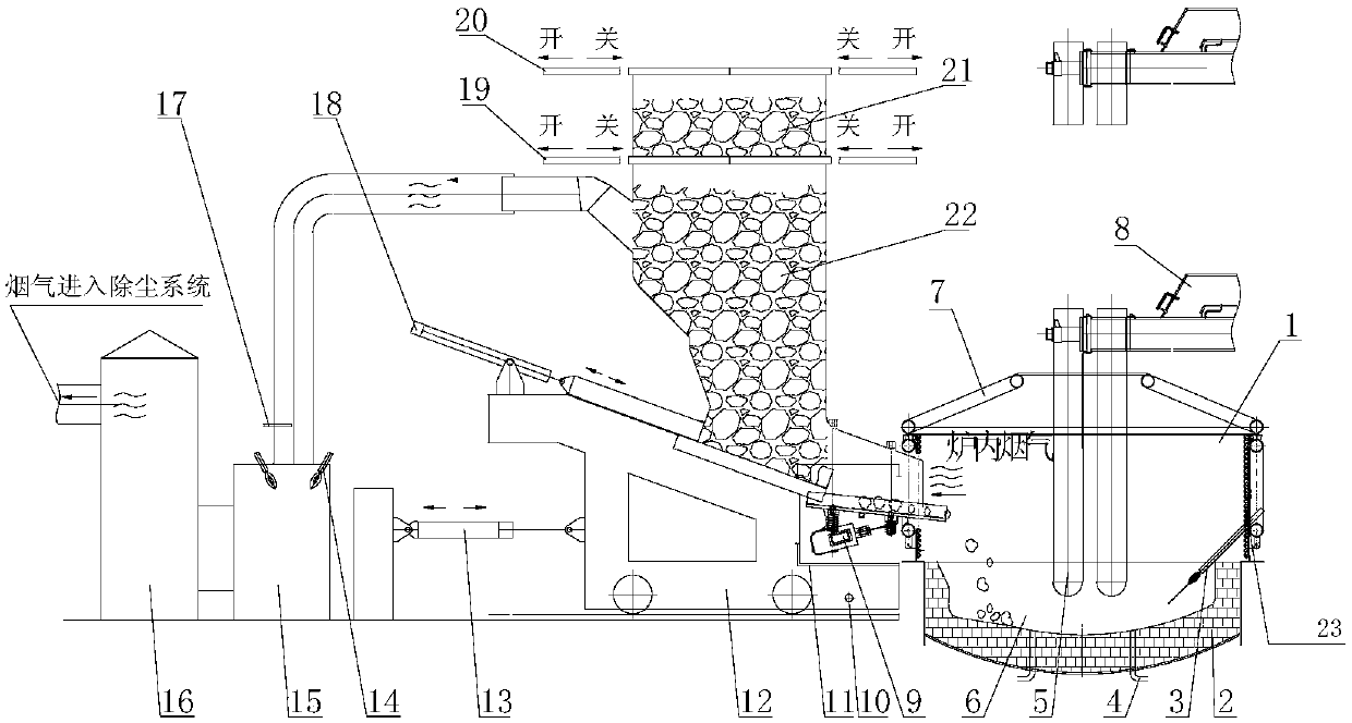
[0067] This embodiment provides a steelmaking device for continuously preheating steel scrap, and its structural schematic diagram is as follows figure 1 shown, from figure 1 As can be seen, the device includes:

[0068] Scrap steel shaft, the scrap steel shaft is divided into scrap steel charging shaft 21 and scrap steel preheating shaft 22 by the second shaft gate 19 arranged on its upper part, and the top of scrap steel charging shaft 21 is provided with the first shaft gate 20 in order to separate it seal;

[0069] The shaft base 12 is used to support the scrap steel shaft; the shaft base 12 is also provided with a locking device 10 for locking the shaft base 12;

[0070] Shaft mobile device 13, this shaft mobile device 13 is connected with shaft base 12, is used for pulling shaft base 12 so that scrap steel shaft is separated from furnace body 1 of electric arc furnace;

[0071] An electric arc furnace, the electric arc furnace includes a furnace cover 7 arranged up an...

Embodiment 2

[0084] This embodiment provides a steelmaking process for continuously preheating steel scrap, which is realized by using the steelmaking device for continuously preheating steel scrap provided in Example 1, wherein the steelmaking process for continuously preheating steel scrap includes the following Specific steps:

[0085] Step (1): Open the furnace lid for the first time to charge.

[0086] This step is mainly applicable to the first smelting of the new furnace lining, and is used to produce remaining steel in the furnace. When there is already remaining steel in the furnace, it starts from step (2). This step (1) specifically includes the following steps: first, the conductive cross arm is raised to lift the electrode into the furnace cover of the electric furnace, and the furnace cover and the electrode pass through the rotating mechanism ( figure 1 Unscrew together, use the scrap steel basket to add a certain amount of scrap steel (the amount that meets the requirement...


PUM


Abstract

The invention provides a steelmaking device and process for continuously preheating scrap steel. The device comprises a scrap steel vertical shaft, an electric arc furnace and a vibrating feeder, wherein the scrap steel vertical shaft is divided into a scrap steel charging vertical shaft and a scrap steel preheating vertical shaft by a second vertical shaft gate arranged at the upper part of the scrap steel vertical shaft, and the top of the scrap steel charging vertical shaft is provided with a first vertical shaft gate for sealing the scrap steel charging vertical shaft; the electric arc furnace comprises a furnace cover and a furnace body which are arranged up and down, wherein the furnace body comprises an upper furnace shell, a molten pool and a lower furnace shell which are sequentially arranged up and down, a multifunctional furnace wall gun is arranged on the upper furnace shell, and a flue gas outlet formed in the upper furnace shell of the electric arc furnace is connected with an inlet of a scrap steel preheating vertical shaft flue through a flue; and the vibrating feeder is used for feeding the preheated scrap steel into the molten pool of the electric arc furnace. Thesteelmaking device and process for continuously preheating the scrap steel is the scrap steel steelmaking device and process combining scrap steel preheating, electric arc heating, primary energy fluxing, furnace bottom blowing stirring (bottom blowing) and efficient oxygen blowing.

Description

technical field [0001] The invention relates to a steelmaking device and process for continuously preheating scrap steel, belonging to the technical field of iron and steel metallurgy. Background technique [0002] Divided from the charging mode, the current electric furnace technology and equipment for steelmaking with scrap steel can be divided into cold charging and hot charging. Cold charging means that scrap steel is directly loaded into the furnace for smelting without preheating, and hot charging That is, steel scrap needs to be preheated before being loaded into the furnace for smelting. Most traditional electric arc furnaces use cold charging for smelting. During the smelting process, high-temperature arcs are mainly used to melt scrap steel and heat molten steel. However, the arc damages the scrap steel greatly, and the melting noise is loud. In the later stage of smelting, a large amount of oxygen blowing and carbon injection and a large amount of manufacturing ar...

Claims


Application Information

Patent Timeline
IPC IPC(8): C21C5/52
CPCC21C5/527Y02P10/20
Inventor 李佳辉王佳潘宏涛常旭李强耿明山李传民韩柏金李博安邦
Owner MCC CAPITAL ENGINEERING & RESEARCH
Why Eureka
Try Eureka