Magnetic levitation track beam tensioning protection device and protection method
A protective device and track beam technology, which is applied to tracks, roads, bridges, etc., can solve problems such as potential safety hazards, broken prestressed tendons, fragments, and parts flying out, and achieve the effect of ensuring construction safety
- Summary
- Abstract
- Description
- Claims
- Application Information
AI Technical Summary
Problems solved by technology
Method used
Image
Examples
Embodiment 1
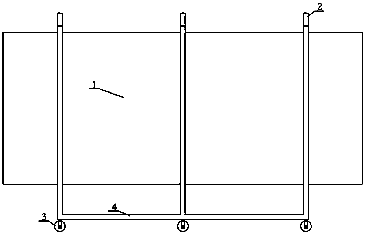
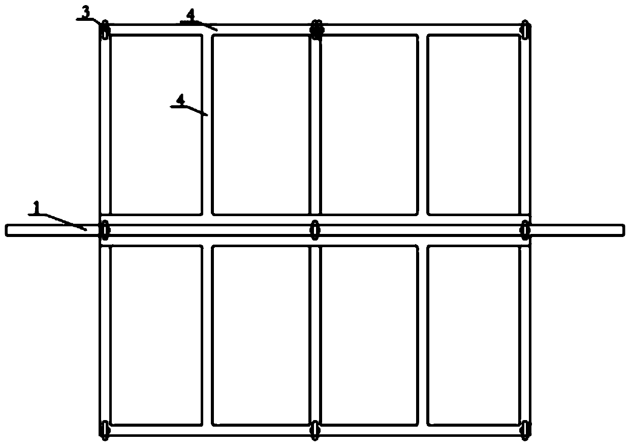
[0023] like figure 1 Shown, in this embodiment, a kind of maglev track beam tension protection device, support frame and the protection steel plate 1 that is arranged on the support frame, described support frame includes bottom frame 4 and two rows are arranged on the bottom frame 4 Supporting columns 2, the protective steel plate 1 is arranged between two rows of supporting columns 2.
[0024] When performing prestressed tensioning on the magnetic levitation track beam, the protective devices are integrally arranged at both ends of the magnetic levitation track beam, so that the protective steel plates 1 are aligned with the steel strands used for tensioning. If the steel strand breaks or slips due to an accident, the steel strand will fly out due to the pre-loaded tension, or the part where the magnetic levitation track beam contacts the steel strand will be broken and fly out fragments, the steel strands can be blocked by using the protective steel plate 1 to prevent the ...
Embodiment 2
[0026] On the basis of the above embodiments, in this embodiment, the protective steel plate 1 is fixedly connected with the support column 2 . In this way, the reliable connection between the protective steel plate 1 and the supporting column 2 can be ensured, and the ability of the protective steel plate 1 to be prevented from moving randomly, resulting in the reduction of the ability to block steel strands and debris.
[0027] In this embodiment, the distance between the two rows of support columns 2 is equal to the thickness of the protective steel plate 1 , and the protective steel plate 1 is welded or screwed to the support column 2 . This facilitates the positioning and installation of the protective steel plate 1 .
[0028] The protective steel plate 1 is located on the centerline of the bottom frame 4 , and the width of the bottom frame 4 is greater than half of the width of the protective steel plate 1 . In this way, the overall center of gravity of the protective d...
Embodiment 3
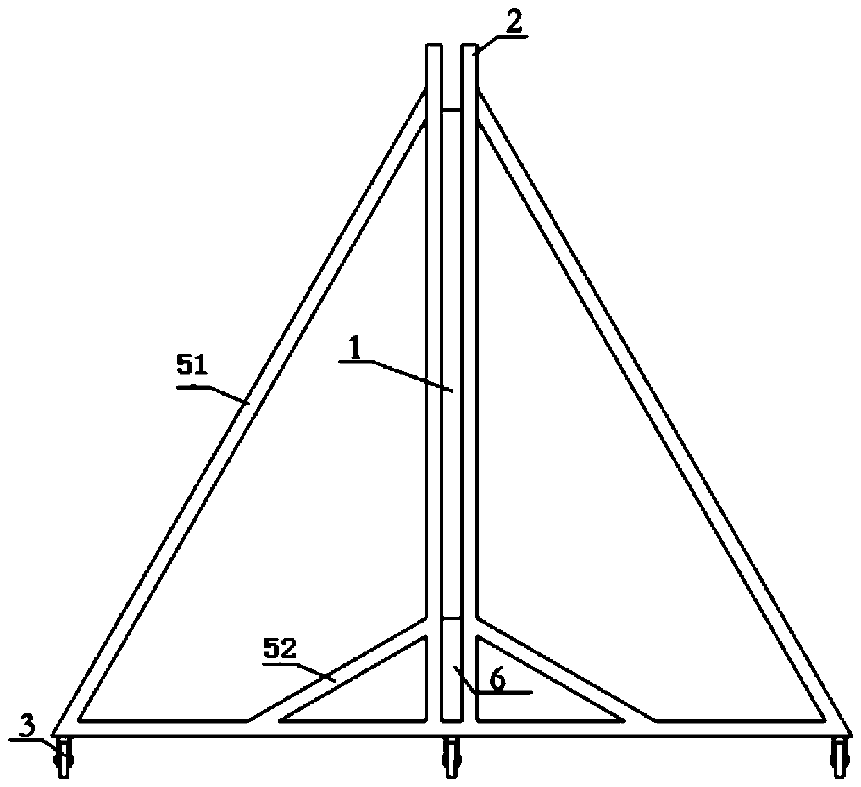
[0030] On the basis of the above embodiments, in this embodiment, the bottom frame 4 is provided with several edge braces 51 connected to the support columns 2 at the edges on both sides of the protective steel plate 1 . Utilizing the edge brace 51 can make the support column 2, the bottom frame 4, and the edge brace 51 form a triangular structure, thereby improving the overall stability of the protective device and the impact resistance of the protective steel plate 1, and avoiding the occurrence of shocks when the protective steel plate 1 bears the impact force. deformed or toppled over.
[0031] In this embodiment, the bottom frame 4 is provided with an intermediate brace 52 connected to the middle or below the middle of the support column 2 . The support column 2 , the bottom frame 4 , and the middle diagonal brace 52 can form a triangular structure with a small area by using the middle diagonal brace 52 , which can further enhance the overall stability of the protective d...
PUM
 Abstract
Description
Claims
Application Information
 - R&D
- Intellectual Property
- Life Sciences
- Materials
- Tech Scout
- Unparalleled Data Quality
- Higher Quality Content
- 60% Fewer Hallucinations
Browse by: Latest US Patents, China's latest patents, Technical Efficacy Thesaurus, Application Domain, Technology Topic, Popular Technical Reports.
© 2025 PatSnap. All rights reserved.Legal|Privacy policy|Modern Slavery Act Transparency Statement|Sitemap|About US| Contact US: help@patsnap.com


