
A method and device for real-time monitoring of ground pressure disasters in mining surrounding rock

A real-time monitoring and surrounding rock technology, applied in mining equipment, measurement, mining equipment, etc., can solve problems such as uneven distribution, single monitoring means, and difficulty in knowing ground pressure disasters, achieving high complementarity of monitoring quantities and simple device operation , Ease of on-site operation

Active Publication Date: 2020-12-15
UNIV OF SCI & TECH BEIJING
View PDF8 Cites 0 Cited by
  • Summary
  • Abstract
  • Description
  • Claims
  • Application Information

AI Technical Summary

Problems solved by technology

At present, the monitoring methods for deep ground pressure disasters are single, and the distribution is evacuated, and the data reflect the nature of the disaster is not clear, resulting in inaccurate prediction or uncertain location of ground pressure disasters
[0003] At present, the means of monitoring ground pressure disasters in deep mining mainly focus on roof pressure, roadway deformation, ground stress, structural stress, drilling cuttings, and microseismic. However, certain types of monitoring often focus on stress or deformation, which cannot fully describe and reflect the characteristics of disaster occurrence. The distribution of monitors is not uniform and the number is small. There are often omissions in monitoring locations and difficult reflection of monitoring data. The problem of the characteristics of the disaster makes it difficult to accurately know the ground pressure disaster in advance, and there is a lack of effective combined monitoring of monitoring means to more accurately know the location of the ground pressure disaster and the information before it occurs, so that it can be used on the spot according to the actual situation. - Light-temperature-electricity-acoustic-seismic co-location combined monitoring method solves the problems of missing monitoring locations and missing disaster characteristics of monitoring data

Method used


Image

  • A method and device for real-time monitoring of ground pressure disasters in mining surrounding rock

Examples


Embodiment Construction

[0032] In order to better understand the technical solutions of the present invention, the embodiments of the present invention will be described in detail below in conjunction with the accompanying drawings.

[0033] It should be clear that the described embodiments are only some of the embodiments of the present invention, not all of them. Based on the embodiments of the present invention, all other embodiments obtained by persons of ordinary skill in the art without creative efforts fall within the protection scope of the present invention.

[0034] Terms used in the embodiments of the present invention are only for the purpose of describing specific embodiments, and are not intended to limit the present invention. As used in the embodiments of the present invention and the appended claims, the singular forms "a", "said" and "the" are also intended to include the plural forms unless the context clearly indicates otherwise.

[0035] The present invention provides a real-tim...


PUM


Abstract

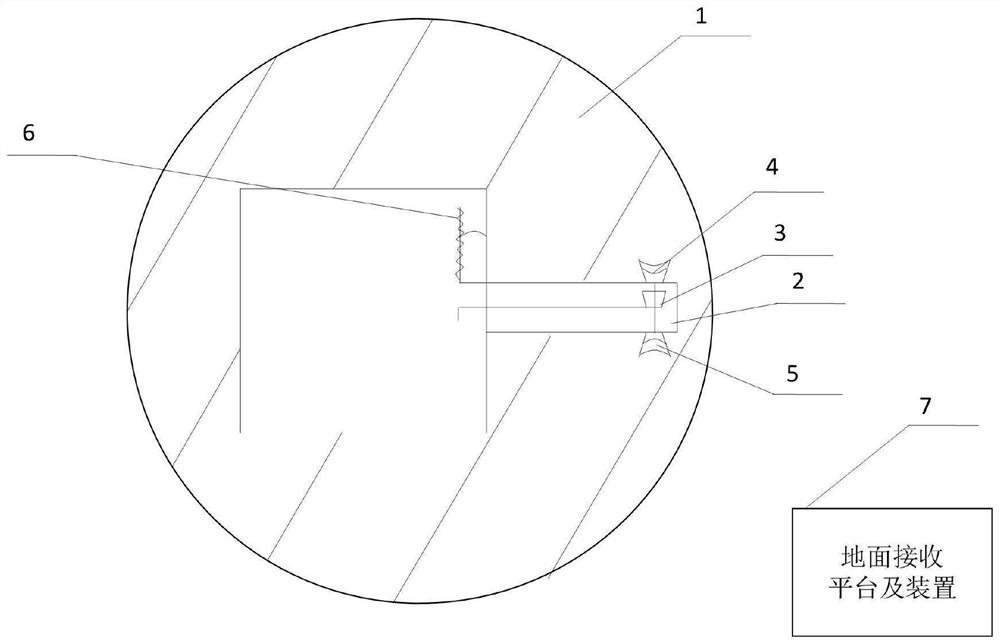
The invention provides a mining surrounding rock ground pressure disaster real-time monitoring method and device. According to the method, in the deep exploiting process, the drilling following test is conducted on the mining surrounding rock, and the drilling following mechanical response amount is obtained to represent mining surrounding rock stress and strength distribution; an optical and temperature sensor is arranged in a drilled hole, and the mining surrounding rock deformation and temperature conditions in the drilled hole are obtained in real time; an electric charge and sound emission sensor is arranged at the same position, and mining surrounding rock electric charges and sound emission events are collected in real time; and meanwhile, a slight shock sensor is arranged at the same position in the drilled hole, and the mining surrounding rock large-range energy condition is monitored in real time. Drilling mining surrounding rock same-position test data are transmitted to a roadway and then wirelessly transmitted to a ground receiving platform and device through a roadway receiving end, then, data tidying and analyzing are conducted, and the mining surrounding rock groundpressure disaster prediction result is issued in time.

Description

【Technical field】 [0001] The invention belongs to the technical field of prediction and prevention of ground pressure disasters in deep mining, and specifically relates to a method and device for real-time monitoring of rock pressure disasters in mining surrounding rocks, in particular to a tactile force-light-temperature-electricity - Acoustic-seismic co-location real-time monitoring method and device. 【Background technique】 [0002] Ground pressure disasters in deep mining severely destroy roadways or working faces, posing a great threat to on-site work. Before excavation, the underground rock mass of the mine bears the weight of the overlying strata and other forces and is in a balanced state, which is called the original stress balance state. Once the ore mass is excavated or there is an excavation project nearby, its original stress balance state will be destroyed, and the stress in the ore mass will be redistributed to achieve a new balance. In the process, the second...

Claims


Application Information

Patent Timeline
Patent Type & Authority Patents(China)
IPC IPC(8): E21F17/18E21B47/00E21B47/07
CPCE21B47/00E21F17/18
Inventor 吕祥锋
Owner UNIV OF SCI & TECH BEIJING
Learn More