
Splitting device and roadway floor pressure relief method

A technology of roadway and floor, which is applied in earth-moving drilling, surface mining, underground mining, etc., can solve the problems of inability to operate in parallel, difficult to handle, and large amount of engineering, so as to improve the splitting depth, shorten the operation time, and shorten the operation time. Effect

Active Publication Date: 2021-07-02
内蒙古伊泰广联煤化有限责任公司 +1
View PDF4 Cites 0 Cited by
  • Summary
  • Abstract
  • Description
  • Claims
  • Application Information

AI Technical Summary

Problems solved by technology

[0003] However, the prior art is complicated in technology, large in engineering quantity and great in safety hazard.
First of all, after the drilling is completed, the water in the hole needs to be blown dry, then the powder is charged manually, and finally the hole is sealed with gun mud. The process is very complicated.
Simultaneous charging and detonation poses a high safety risk, and it is difficult to deal with blind shots, and it cannot be operated in parallel with other projects, which brings risks to mine safety production

Method used


Image

  • Splitting device and roadway floor pressure relief method
  • Splitting device and roadway floor pressure relief method
  • Splitting device and roadway floor pressure relief method

Examples


Embodiment 1

[0070] Such as Figure 4 As shown, a kind of roadway floor pressure relief method provided in this embodiment includes:

[0071] Step S101: using a drilling rig to drill holes at the two bottom corners of the roadway;

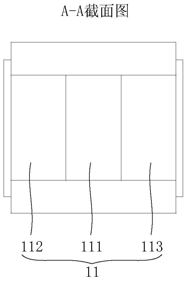
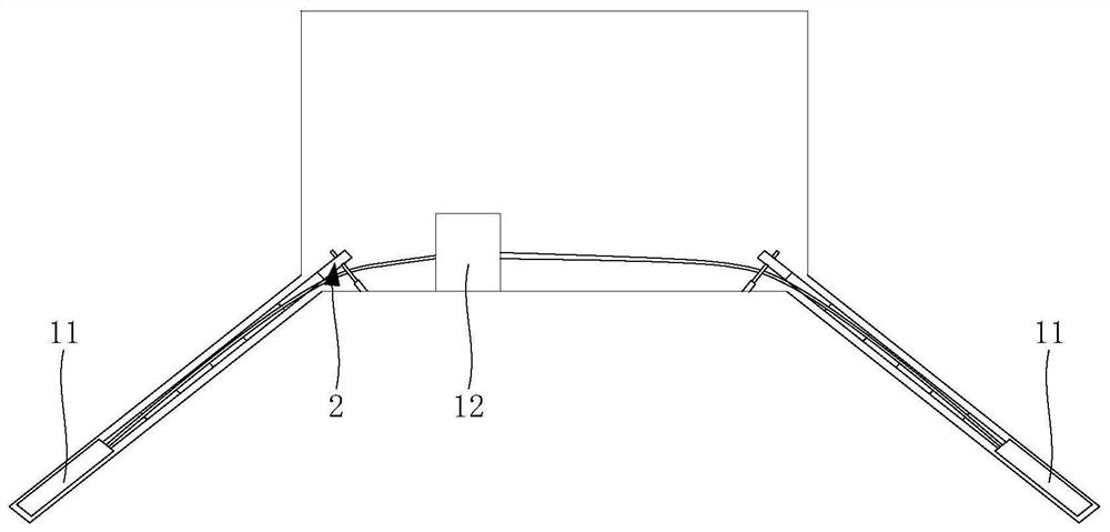
[0072] Step S1021: extending the hydraulic jack 11 in the splitting rod 1 into the bottom of the hole by adjusting the assembly 2;

[0073] Step S103: splitting the rock around the bottom of the hole by hydraulic jack;

[0074] Step S104: Shorten the distance between the hydraulic jack 11 and the hole opening by adjusting the component 2, and use the hydraulic jack to split the rocks around the hydraulic jack 11.

[0075] In order to describe the pressure relief method for the above-mentioned roadway floor more clearly, it can be specifically described as Figure 4 The method shown is described as an example. Such as Figure 4 As shown, first perform step S101 and use a drilling rig to drill holes at the two bottom corners of the roadway, with a hole diame...

Embodiment 2

[0077] Such as Figure 5 As shown, a kind of roadway floor pressure relief method provided in this embodiment includes:

[0078] Step S101: using a drilling rig to drill holes at the two bottom corners of the roadway;

[0079] Step S1021: extending the hydraulic jack 11 in the splitting rod 1 into the bottom of the hole by adjusting the assembly 2;

[0080] Step S1022: fixing the adjustment assembly 2 on the floor of the roadway;

[0081] Step S103: splitting the rock around the bottom of the hole by hydraulic jack;

[0082] Step S104: Shorten the distance between the hydraulic jack 11 and the hole opening by adjusting the component 2, and use the hydraulic jack to split the rocks around the hydraulic jack 11.

[0083] In order to describe the pressure relief method for the above-mentioned roadway floor more clearly, it can be specifically described as Figure 4 The method shown is described as an example. Such as Figure 4 As shown, first perform step S101 and use a dri...


PUM


Abstract

The invention provides a splitting device and a roadway bottom plate pressure relief method, which relate to the technical field of roadway rock burst prevention and control. The splitting device provided by the invention includes a splitting rod and an adjustment assembly connected with the splitting rod. In order to extend into the hole and split the rock, the adjusting assembly is used to adjust the distance of the splitting rod relative to the hole opening along the extending direction of the hole. The splitting device provided by the invention can statically split the floor rock formation, shorten the working time, has strong controllability, replaces traditional drilling and blasting for pressure relief, and has high safety.

Description

technical field [0001] The invention relates to the technical field of roadway rock burst prevention and control, in particular to a splitting device and a roadway floor pressure relief method. Background technique [0002] Nowadays, floor blasting is usually used to relieve pressure to prevent floor impact. First, a drilling rig is used to drill holes at the two bottom corners of the roadway, and then artificially load explosives into the holes. The charge length is generally not less than 1 / 3 of the hole depth, and then detonate. . [0003] However, the prior art is complicated in process, large in engineering quantity and large in safety hazard. First of all, after the drilling is completed, the water in the hole needs to be blown dry, then the powder is charged manually, and finally the hole is sealed with gun mud. The process is very complicated. At the same time, the explosives are charged and detonated, which has a great safety risk. If there is a blind shot, it is ...

Claims


Application Information

Patent Timeline
Patent Type & Authority Patents(China)
IPC IPC(8): E21C41/18E21C37/08
CPCE21C37/08E21C41/18
Inventor 吴修光吕福廷刘阳军
Owner 内蒙古伊泰广联煤化有限责任公司
Learn More