
Outer fin heat exchange tube with spiral inner core and manufacturing method of outer fin heat exchange tube

A manufacturing method and technology of heat exchange tubes, which are applied in the direction of tubular elements, heat exchange equipment, lighting and heating equipment, etc., can solve the problem that the compound agent between the inner fin and the base tube is difficult to clean, and the heat exchange tube is limited by the width of the inner fin coil. Limitation, high cost of heat exchange tubes, etc., to achieve the effect of small fluid resistance, increase cleaning process, and improve heat exchange efficiency

Inactive Publication Date: 2020-06-23
香港环能有限公司
View PDF5 Cites 4 Cited by
  • Summary
  • Abstract
  • Description
  • Claims
  • Application Information

AI Technical Summary

Problems solved by technology

[0004] The first purpose of the present invention is to provide a manufacturing method of an outer-finned heat exchange tube with a spiral inner core in view of the defects and deficiencies of the prior art, which solves the problem that the heat exchange tube is limited by the width of the inner fin coil in the prior art. Restrictions, and the difficulty of cleaning the compound residue between the inner fin and the base tube, resulting in high cost and limited application of heat exchange tubes

Method used


Image

  • Outer fin heat exchange tube with spiral inner core and manufacturing method of outer fin heat exchange tube
  • Outer fin heat exchange tube with spiral inner core and manufacturing method of outer fin heat exchange tube
  • Outer fin heat exchange tube with spiral inner core and manufacturing method of outer fin heat exchange tube

Examples


Embodiment Construction

[0028] The present invention will be described in further detail below in conjunction with the accompanying drawings.

[0029] This specific embodiment is only an explanation of the present invention, and it is not a limitation of the present invention. Those skilled in the art can make modifications to this embodiment as required after reading this specification, but as long as they are within the rights of the present invention All claims are protected by patent law.

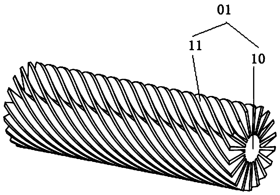
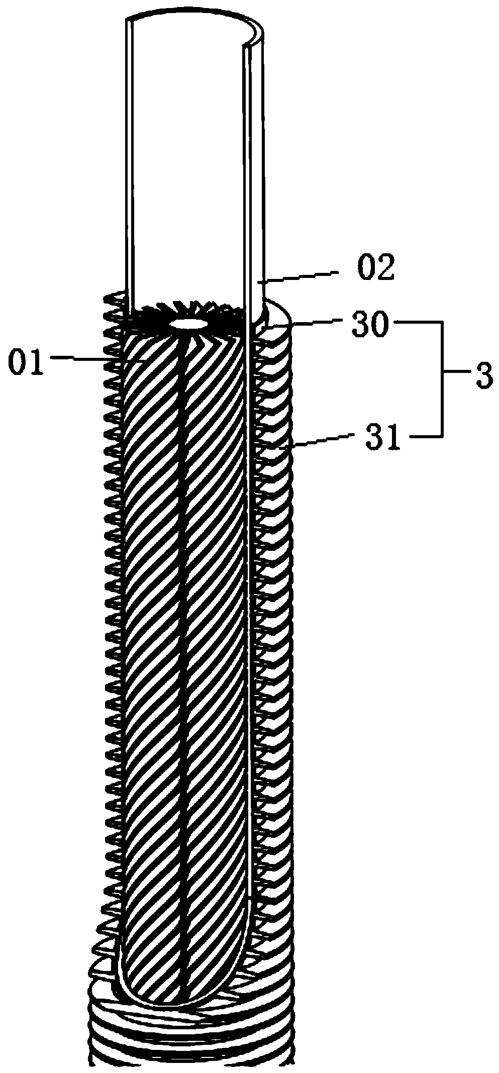
[0030] This embodiment relates to a method for manufacturing an outer-fin heat exchange tube with a spiral inner core, the method comprising: S1: obtaining the spiral inner core 01;

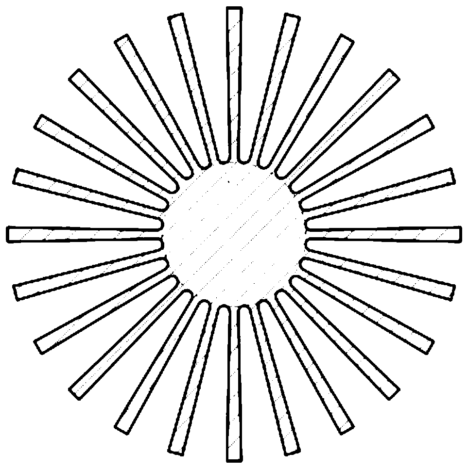
[0031] (1) The aluminum bar with good thermal conductivity and fast heat dissipation is processed into longitudinal fin profiles by hot extrusion, such as figure 1 shown;

[0032] (2) While the profile is relatively hot and easy to deform, the profile extruded at a constant speed is passed through the twisting tool, and the rot...


PUM


Abstract

The invention provides an outer fin heat exchange tube with a spiral inner core, and relates to the technical field of heat exchange. The manufacturing method comprises the following steps of S1, acquiring the spiral inner core: (1) processing into a longitudinal fin profile by adopting a hot extrusion way; and (2) applying rotational torque to the profile extruded at a constant speed through a rotation-shearing tool according to a rotational speed corresponding to a designed screw pitch while the profile is relatively hot and easy to deform, so that a longitudinal fin is spirally deformed toobtain the spiral inner core; S2, compounding the spiral inner core and a base tube: (1) obtaining a cored base tube by a thermal expansion and cold contraction or rolling compounding method; and S3,compounding the cored base tube and an outer fin sleeve: (1) manufacturing an outer sleeve by adopting a hot extrusion way; (2) performing contact-type inserting of the cored base tube in the outer sleeve when the outer sleeve is relatively hot and the internal diameter of the outer sleeve is relatively large, and compounding the outer sleeve and the cored base tube when the outer sleeve is subjected to thermal expansion and cold contraction; and (3), extruding the outer fin on the outer sleeve to manufacture the outer fin heat exchange tube with the spiral inner core. The outer fin heat exchange tube with the spiral inner core overcomes the defects that in the prior art, the length of a corrugated inner fin of a heat exchange tube is limited, trash needs to be cleaned in soldering, the production cost is high, the cycle is long, and the application range is limited.

Description

technical field [0001] The invention relates to the technical field of heat exchange, in particular to an outer-fin heat exchange tube with a spiral inner core and a manufacturing method thereof. Background technique [0002] Finned heat exchange tubes have been widely used in various types of heat exchange equipment and heating equipment. It mainly increases the outer surface area (or inner surface area) of the heat exchange tube by adding fins on the surface of the heat exchange tube, so as to improve purpose of heat transfer efficiency. [0003] Finned tubes used in heat exchangers are roughly divided into two types in terms of structure: one is outer finned tubes, and the other is inner finned tubes, both of which are used to realize heat exchange inside and outside the pipe. At present, there are inner fin-enhanced heat exchange tubes at home and abroad. The inner fins are generally processed into corrugated inner fins through tin-plated thin copper coils (W≤1300mm), a...

Claims


Application Information

Patent Timeline
IPC IPC(8): F28F1/40F28F21/08B21C23/00
CPCB21C23/00F28F1/40F28F21/084F28F21/085
Inventor 许欣平
Owner 香港环能有限公司
Learn More