Raw material grinding equipment for chemical machinery

A technology for chemical machinery and raw materials, applied in the field of raw material grinding equipment for chemical machinery, can solve the problems of easy sticking to the edge of the groove and incomplete grinding, and achieve the effect of complete grinding

Inactive Publication Date: 2020-06-26
张忠余
View PDF4 Cites 3 Cited by
  • Summary
  • Abstract
  • Description
  • Claims
  • Application Information

AI Technical Summary

Problems solved by technology

[0002] In the chemical industry, chemical raw materials are divided into two categories: metallic materials and non-metallic materials. Non-metallic materials mainly include plastics, rubber, glass, ceramics, enamel, and impermeable graphite. These non-metallic materials are used in the chemical industry. It is widely used; these raw materials often need to be ground during the early treatment. When grinding ceramics, the ceramic raw materials in the grinding tank are easy to stick to the edge of the tank under the action of centrifugal force, resulting in incomplete grinding.

Method used


Image

  • Raw material grinding equipment for chemical machinery
  • Raw material grinding equipment for chemical machinery
  • Raw material grinding equipment for chemical machinery

Examples


Embodiment 1

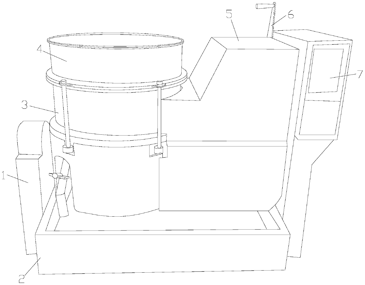
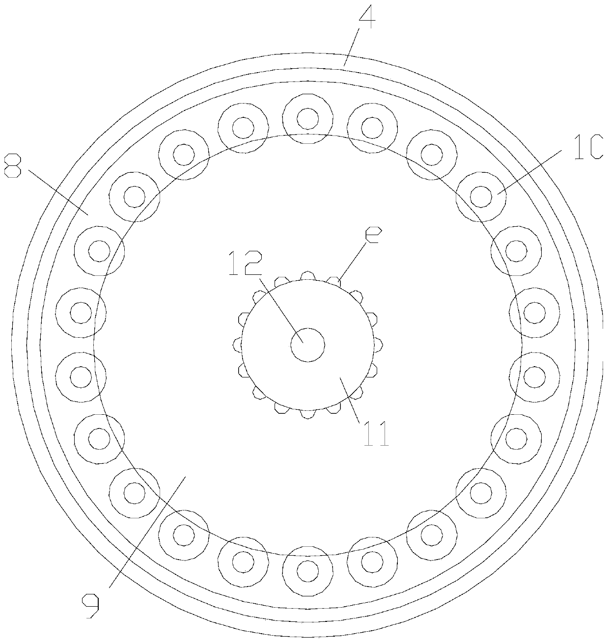
[0030] see Figure 1-Figure 5 , the present invention provides a technical solution for raw material grinding equipment for chemical machinery: its structure includes a frame 1, a water tank 2, a grinding cylinder 3, a top ring 4, a body 5, a rocker 6, and a control panel 7. The frame 1 The bottom of the body is equipped with a water tank 2, the body 5 is movably installed on the frame 1 and is located above the water tank 2, the grinding cylinder 3 is connected to the left side of the body 5, and the top ring 4 passes through four sets of The bolt rod is installed above the grinding cylinder 3, and the rocking lever 6 is installed on the rear end on the right side of the top of the body 5. A control panel 7 is arranged on the right column of the body 5; There is a ring sleeve 8, and twenty-two groups of grinding rollers 10 are equidistantly arranged in the ring sleeve 8, and a grinding groove 9 is arranged in the middle of the ring sleeve 8, and a cylinder 12 is connected in ...

Embodiment 2

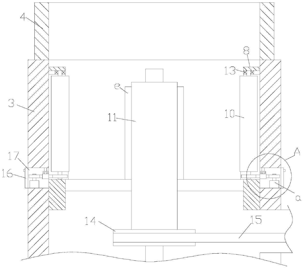
[0033] like Image 6 As shown, on the basis of Embodiment 1, more than two grinding blocks f are evenly and equidistantly arranged on the roller surface of the grinding roller 10, and a central axis h passes through the middle of the grinding roller 10, and both One end of the central shaft h is in interference fit with the bearing seat 13, and the other end is connected with a driven gear c, and the driven gear c is meshed with the inner ring gear a5.

[0034] The driven gear c at the bottom of the grinding roller 10 rotates under the drive of the ring gear a5. The surface of the grinding roller 10 is provided with grinding blocks f. These grinding blocks f can grind the ceramic raw materials to make the ceramic raw materials grind more thoroughly.


PUM


Abstract

The present invention discloses raw material grinding equipment for chemical machinery. The equipment structurally comprises a rack, a water containing groove, a grinding cylinder, a top ring, a machine body, a rocker rod and a control panel, wherein the bottom of the rack is provided with the water containing groove; the machine body is movably installed on the rack and located above the water containing groove; the grinding cylinder is connected with the left side of the machine body; the top ring is installed above the grinding cylinder through four groups of bolt rods; the rocker rod is installed on the back end of the right side of the top of the machine body; and a column on the right side of the machine body is provided with the control panel. The equipment has the beneficial effects that a ring sleeve in the grinding cylinder is internally provided with twenty-two groups of grinding rollers, the bottoms of the grinding rollers are provided with rotating rings, an external motordrives the rotating rings to rotate, and inner gear rings on the inner sides of the rotating rings can enable the twenty-two groups of grinding rollers to rotate for grinding ceramic raw materials attached to the edge of the groove, thereby preventing the phenomena of insufficient grinding.

Description

technical field [0001] The invention relates to raw material grinding equipment for chemical machinery, which belongs to the field of chemical machinery equipment. Background technique [0002] In the chemical industry, chemical raw materials are divided into two categories: metallic materials and non-metallic materials. Non-metallic materials mainly include plastics, rubber, glass, ceramics, enamel, and impermeable graphite. These non-metallic materials are used in the chemical industry. It is widely used; these raw materials often need to be ground during the early treatment. When grinding ceramics, the ceramic raw materials in the grinding tank will easily stick to the edge of the tank under the action of centrifugal force, resulting in incomplete grinding. Contents of the invention [0003] Aiming at the deficiencies in the prior art, the object of the present invention is to provide a raw material grinding equipment for chemical machinery to solve the problems. [00...

Claims


Application Information

Patent Timeline
Patent Type & Authority Applications(China)
IPC IPC(8): B02C4/10B02C4/42B02C4/30B02C17/04B02C17/18
CPCB02C4/10B02C4/30B02C4/42B02C17/04B02C17/18
Inventor 张忠余
Owner 张忠余
Why Eureka
Try Eureka