Unlock instant, AI-driven research and patent intelligence for your innovation.

Automatic loading and unloading device

A technology of automatic loading and unloading and feeding area, applied in the field of loading and unloading system, can solve the problems of increasing labor cost and increasing the cost of power mechanism.

Active Publication Date: 2020-06-26
POU CHEN CORPORATION
View PDF6 Cites 3 Cited by
  • Summary
  • Abstract
  • Description
  • Claims
  • Application Information

AI Technical Summary

Problems solved by technology

[0003] Since the feeding area of ​​the existing loading and unloading device of the sewing machine is far away from the receiving area and not adjacent to it, the operator must constantly move between the feeding area and the receiving area, or set two The operator will increase the labor cost, and if an additional receiving device is to be installed, an additional power mechanism will be required, which will relatively increase the cost of the power mechanism, and needs to be improved

Method used


Image

  • Automatic loading and unloading device
  • Automatic loading and unloading device
  • Automatic loading and unloading device

Examples


Embodiment Construction

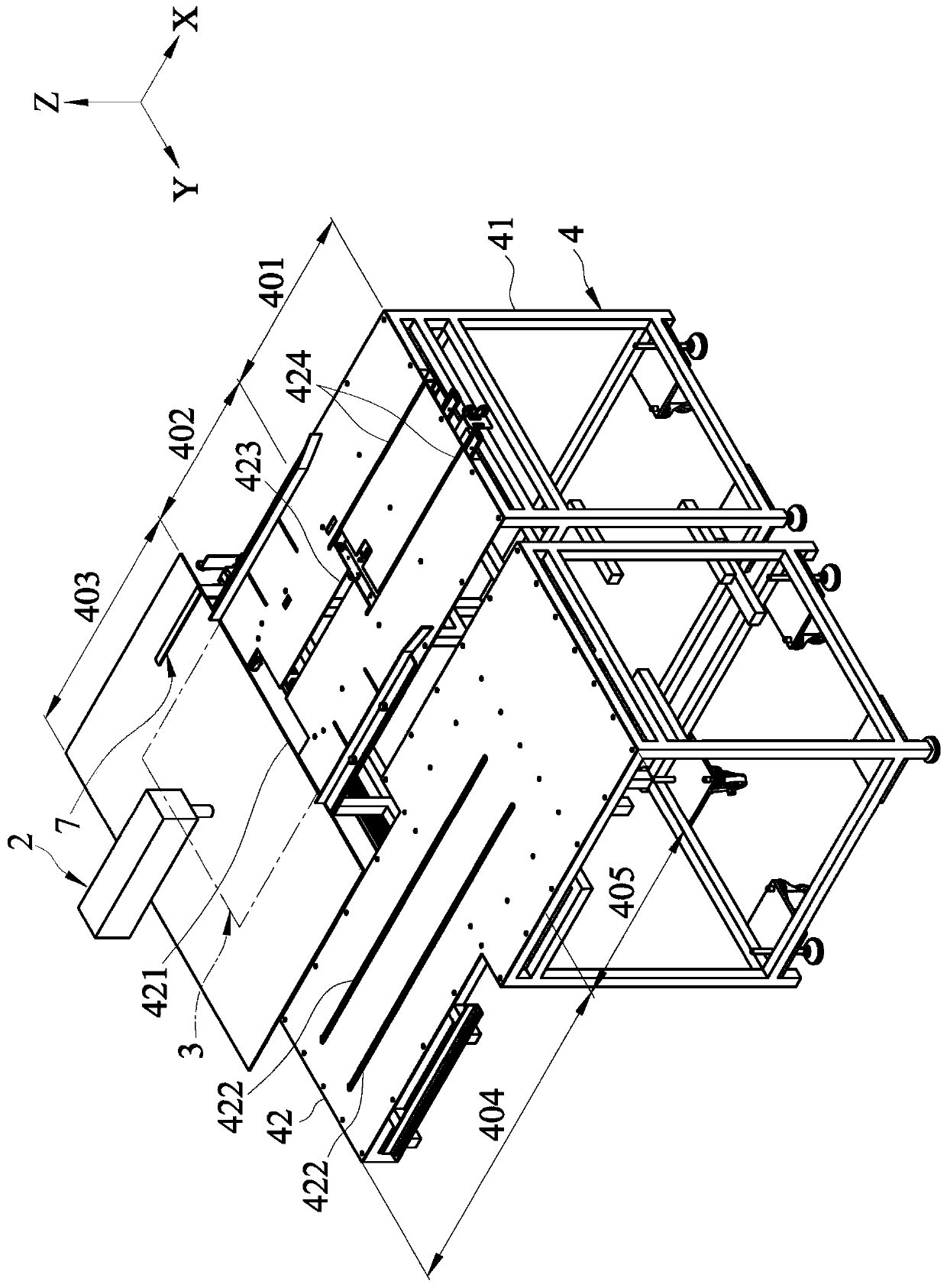
[0036] refer to figure 1 and figure 2 , a first embodiment of the automatic loading and unloading device of the present invention is suitable for installing a sewing machine 2 . The automatic loading and unloading device includes a frame 4 , a loading unit 5 , a loading interlocking unit 6 , an unloading unit 7 , a receiving unit 8 , and a receiving interlocking unit 9 .

[0037] The frame 4 defines a preparation area 401 , a loading area 402 , a processing area 403 , an unloading area 404 and a receiving area 405 . The preparation area 401 , the feeding area 402 and the processing area 403 are arranged in sequence along a transfer direction X, and the processing area 403 is located below the sewing machine 2 . The unloading area 404 is arranged on one side of the processing area 403 along a unloading direction Y. The receiving area 405 is set on the side of the unloading area 404 away from the processing area 403 and adjacent to the preparation area 401 . The transfer di...


PUM


Abstract

An automatic loading and unloading device includes an unloading unit, a receiving unit and a receiving link unit. The frame defines a processing area, an unloading area and a receiving area. The unloading unit includes an unloading slide rail, and an unloading drive group movably disposed on the unloading slide rail for driving at least one plate to move from the processing area to the unloading area. The receiving unit includes a receiving lift group movably disposed on the receiving slide rail for driving the at least one plate to move from the unloading area to the receiving area. The receiving link unit interconnects the unloading drive group and the receiving lift group. When the unloading drive group displaces in a batching direction, the unloading drive group synchronously drives the receiving lift group displace in the unloading direction. Therefore, when batching is performed in the batching direction, the material can be synchronously received in the transfer direction.

Description

technical field [0001] The invention relates to a loading and unloading system, in particular to an automatic loading and unloading device. Background technique [0002] An existing loading and unloading device for needle cars, comprising a workbench, a loading unit and a unloading unit. The workbench defines a feeding area, a processing area, and a receiving area. A needle car is set in the processing area. During processing, the operator can place the movable panel in the feeding area, and transport the movable panel to the processing area through the feeding unit for processing, and finally, deliver the processed movable panel through the unloading unit To the receiving area for the operator to collect finished products in the receiving area. [0003] Since the feeding area of ​​the existing loading and unloading device of the sewing machine is far away from the receiving area and not adjacent to it, the operator must constantly move between the feeding area and the re...

Claims


Application Information

Patent Timeline
IPC IPC(8): B23B15/00
CPCB23Q7/00B23Q2707/003A43D119/00D05B33/00D05B41/00B65G65/02D05B3/12
Inventor 许千昱张文堡王耀鑫洪崇舜
Owner POU CHEN CORPORATION
Features
  • R&D
  • Intellectual Property
  • Life Sciences
  • Materials
  • Tech Scout
  • Unparalleled Data Quality
  • Higher Quality Content
  • 60% Fewer Hallucinations
Learn More