Sectional material and formwork structure

A profile, in-line technology, applied in the direction of formwork/formwork components, building structure, formwork/formwork/work frame, etc., can solve the problems of assembly, disassembly, labor and time, damage, profile deformation, etc., to achieve easy disassembly Effort-saving, easy assembly or disassembly, the effect of reducing the contact area

Pending Publication Date: 2020-06-26
何其佳
View PDF0 Cites 2 Cited by
  • Summary
  • Abstract
  • Description
  • Claims
  • Application Information

AI Technical Summary

Problems solved by technology

[0002] In the prior art, the profiles used for splicing templates are all spliced ​​on large planes, such as figure 1 As shown, the assembly and disassembly are laborious and time-consuming, and only the brutal operation method of knocking and prying can be used during loading and unloading, resulting in deformation and damage of the profile

Method used


Image

  • Sectional material and formwork structure
  • Sectional material and formwork structure
  • Sectional material and formwork structure

Examples


Embodiment 1

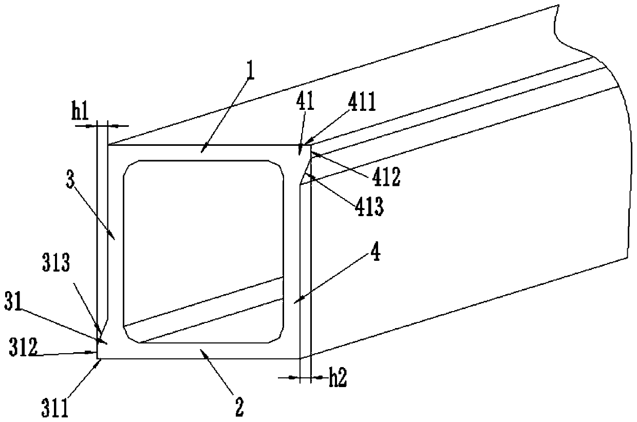
[0063] Such as figure 2 As shown, a profile provided in this embodiment includes a working edge 1 , a first splicing edge 3 , a second splicing edge 4 and a structural edge 2 . The first splicing edge 3 and the second splicing edge 4 are respectively connected to both ends of the working edge 1, and the structural edge 2 is connected between the first splicing edge 3 and the second splicing edge (4) to form Closed structure (square box).

[0064] The outer surface of the end of the first splicing edge 3 away from the working edge 1 is provided with a protruding first splicing edge 31 along the length direction, and the second splicing edge 4 is adjacent to the outer surface of the end of the working edge 1 A second splicing edge 41 protruding along the length direction is provided on the top, and the protruding height h1 of the first splicing edge 31 is equal to the protruding height h2 of the second splicing edge 41 .

[0065] The first joint edge 3 includes a first top su...

Embodiment 2

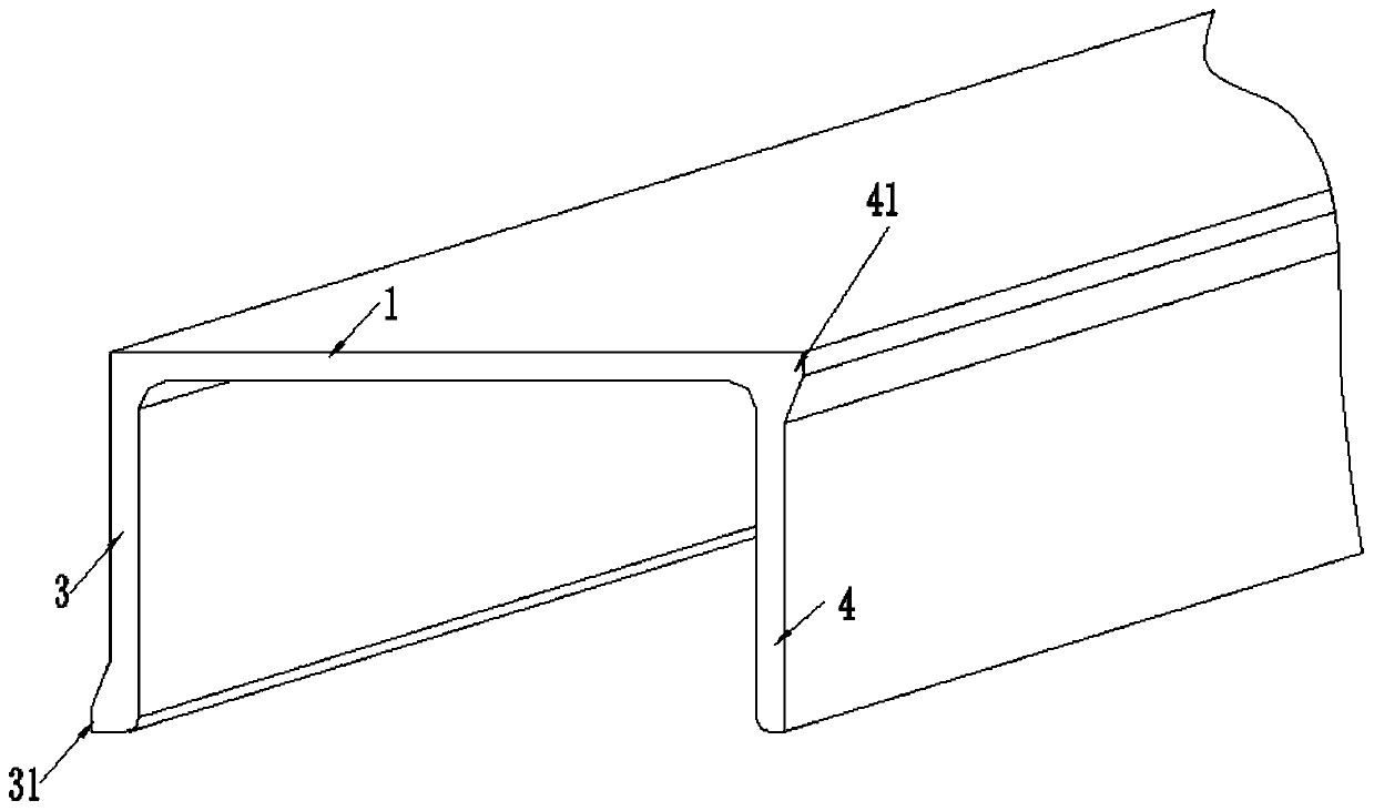
[0068] Such as image 3 As shown, a profile provided in this embodiment includes a working edge 1, a first splicing edge 3 and a second splicing edge 4, the first splicing edge 3 is connected to one end of the working edge 1, and the second splicing edge The side 4 is connected to the other end of the working side 1, and the working side 1, the first joining side 3 and the second joining side 4 form a U-shaped structure with one side closed and one side open.

[0069] The outer surface of the end of the first splicing edge 3 away from the working edge 1 is provided with a protruding first splicing edge 31 along the length direction, and the second splicing edge 4 is adjacent to the outer surface of the end of the working edge 1 A second splicing rib 41 protruding from the upper portion is provided along the length direction. The structures of the first joint edge 31 and the second joint edge 41 are the same as those in the first embodiment.

Embodiment 3

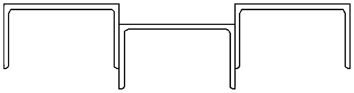
[0071] Such as Figure 4 As shown, the second embodiment is repeated. The difference from the second embodiment is that a first groove 33 is provided on the outer surface of the first joint edge 3, and a second groove 33 is provided on the outer surface of the second joint edge 4. Groove 43. Both the first groove 33 and the second groove 43 extend along the length direction of the profile.

[0072] The number of the first grooves 33 is multiple, the number of the second grooves 43 is multiple, the positions and opening sizes of the first grooves 33 and the second grooves 43 All symmetrical.


PUM


Abstract

The invention provides a sectional material and a formwork structure. The sectional material is of a closed structure formed by sequentially connecting a working edge, a first splicing edge, a structural edge and a second splicing edge end to end, or the sectional material is of an open structure formed by the working edge, the first splicing edge and the second splicing edge. When the sectional material is of the open structure, the first splicing edge and the second splicing edge are connected to the two ends of the working edge respectively. The outer surface of the tail end or near-tail end, away from the working edge, of the first splicing edge is provided with a first splicing rib formed by protruding in the length direction, the outer surface of the tail end or near-tail end, closeto the working edge, of the second splicing edge is provided with a second splicing rib formed by protruding in the length direction, and the protruding height h1 of the first splicing rib is equal tothe protruding height h2 of the second splicing rib. Compared with the related art, the sectional material can be easily spliced or disassembled under the effect of the splicing ribs, and as the contact area is reduced, sectional materials can be spliced more closely.

Description

technical field [0001] The invention relates to the technical field of building formwork, in particular to a profile and formwork structure. Background technique [0002] In the prior art, the profiles used for splicing templates are all spliced ​​on large planes, such as figure 1 As shown, it is laborious and time-consuming to assemble and disassemble, and only the brutal operation method of knocking and prying can be used during loading and unloading, resulting in deformation and damage of the profile. [0003] In addition, define the direction vocabulary mentioned in this case. In this field, the directions generally recognized by technical personnel are: [0004] Length direction: the direction along the length of the profile. Contents of the invention [0005] The purpose of the present invention is to provide a profile and formwork structure that can be easily assembled or disassembled. [0006] The first technical solution to solve the above technical problems pr...

Claims


Application Information

Patent Timeline
Patent Type & Authority Applications(China)
IPC IPC(8): E04G9/02E04G9/06E04G9/05E04G13/00E04G13/02E04G17/00E04G17/02E04G17/04
CPCE04G9/02E04G9/05E04G9/06E04G13/00E04G13/021E04G17/00E04G17/001E04G17/02E04G17/04E04G17/042E04G2009/028E04G2017/008
Inventor 何其佳
Owner 何其佳
Why Eureka
Try Eureka