Control system for internal combustion engine

A control system, technology for internal combustion engines, used in engine control, fuel injection control, internal combustion piston engines, etc.

Inactive Publication Date: 2020-06-26
TOYOTA JIDOSHA KK
View PDF6 Cites 0 Cited by
  • Summary
  • Abstract
  • Description
  • Claims
  • Application Information

AI Technical Summary

Problems solved by technology

Therefore, there are limitations in the solu

Method used


Image

  • Control system for internal combustion engine
  • Control system for internal combustion engine
  • Control system for internal combustion engine

Examples


Embodiment Construction

[0044] Hereinafter, embodiments of the present disclosure will be described with reference to the accompanying drawings. It should be noted that in the respective drawings, the same reference numerals are attached to the same elements, and repeated descriptions are omitted. In addition, the present disclosure is not limited to the following examples.

[0045] 1. Example of the structure of the control system

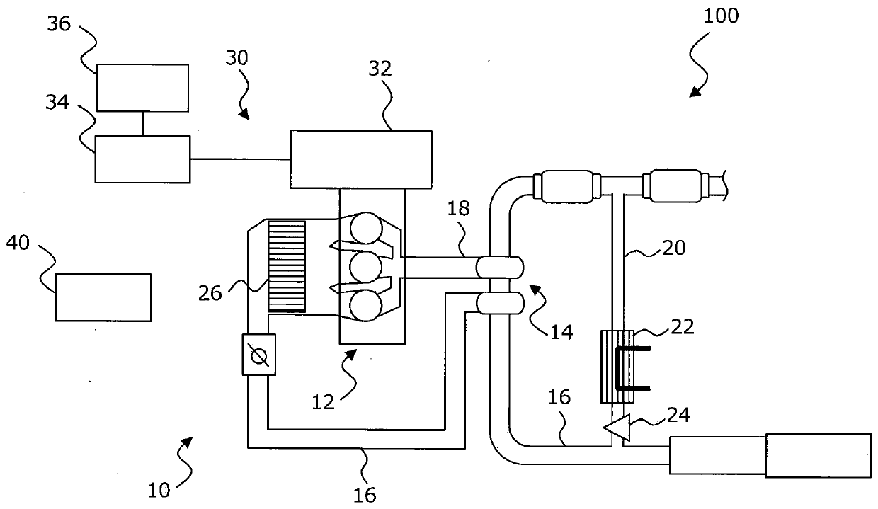
[0046] A control system for an internal combustion engine according to an embodiment is mounted on a vehicle. figure 1 is a view for illustrating a first configuration example of the control system according to the embodiment. figure 1 The illustrated control system 100 is a hybrid powertrain system including an engine system 10 and a rotating electrical system 30 .

[0047] 1.1 Engine system

[0048] Engine system 10 includes engine 12 . The engine 12 is a diesel engine or a gasoline engine. Engine 12 is depicted as an inline three cylinder engine. However, the n...


PUM


Abstract

The present invention relates to a control system for an internal combustion engine. The control system performs the corrosion control periodically to corrode the whole surface of an engine componentin contact with a condensed water. The corrosion control includes a set of front half control and a rear half control. The first half control is performed within a first time period from the time (t2)to the time (t3), in the front half control, the engine (12) is operated in a predetermined operating area, and the rear half control is performed within a second time period from the time (t3) to the time (t4).

Description

[0001] Cross References to Related Applications [0002] This application claims priority under 35 U.S.C. §119 to Japanese Patent Application No. 2018-236771 filed on December 18, 2018. The entire content of this application is hereby incorporated by reference. technical field [0003] The present disclosure relates to a control system for an internal combustion engine (hereinafter also simply referred to as "engine"). Background technique [0004] JP 2010-121574 A discloses a control system for an engine including an EGR (Exhaust Gas Recirculation) device. In this conventional system, when a predetermined stop condition is satisfied, automatic stop control of the engine is performed in principle. However, in this conventional system, if the temperature of the wall surface of the EGR passage is lower than a predetermined temperature, execution of the automatic stop control is prohibited. In short, even if the stop condition is satisfied, the engine is operated and the aut...

Claims


Application Information

Patent Timeline
IPC IPC(8): F02D41/00F02D29/06F02D29/02
CPCF02D41/0065F02D29/06F02D29/02F02M26/50F02M26/74F02M26/06F02D41/0055F02D2041/1472B60W20/15B60W20/16B60W2555/20Y02T10/40F02D45/00B60W20/20F02D43/04B60W20/40
Inventor 小林淳也
Owner TOYOTA JIDOSHA KK
Why Eureka
Try Eureka