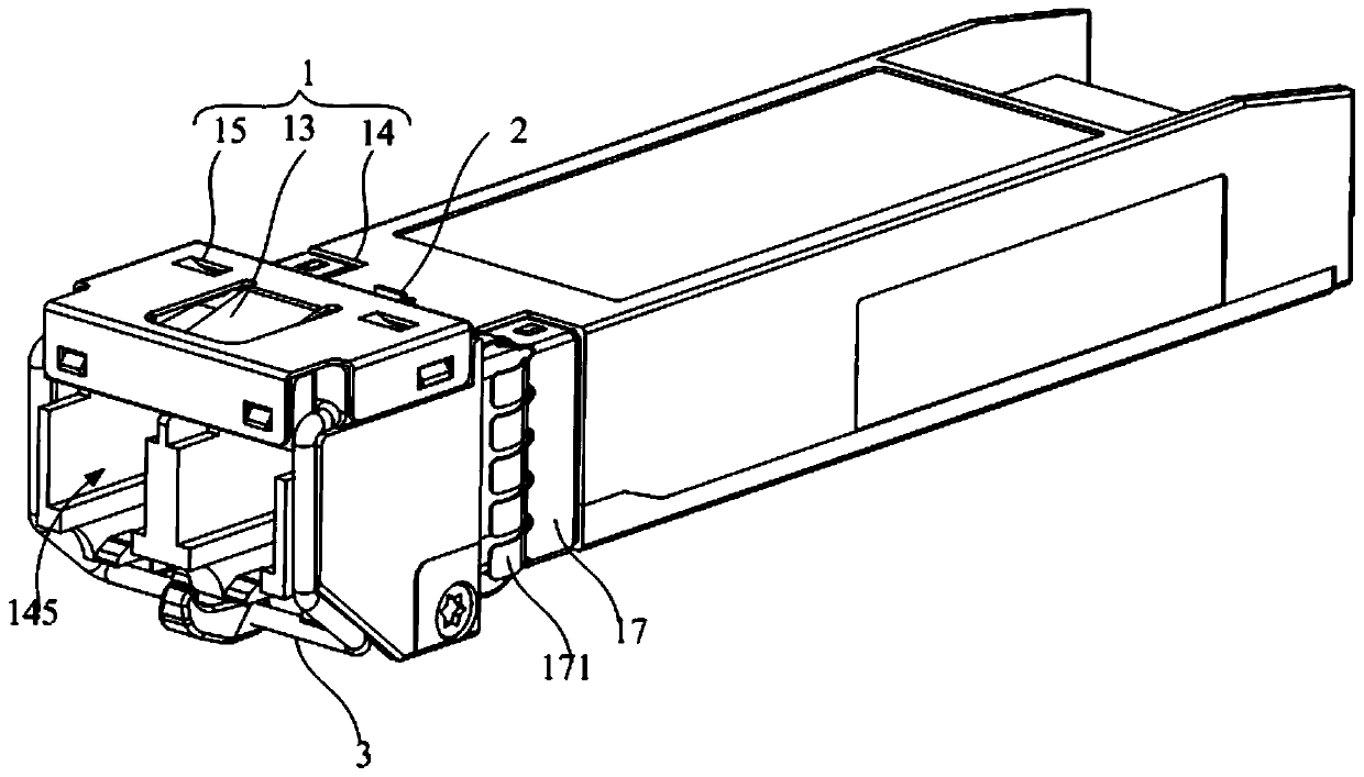
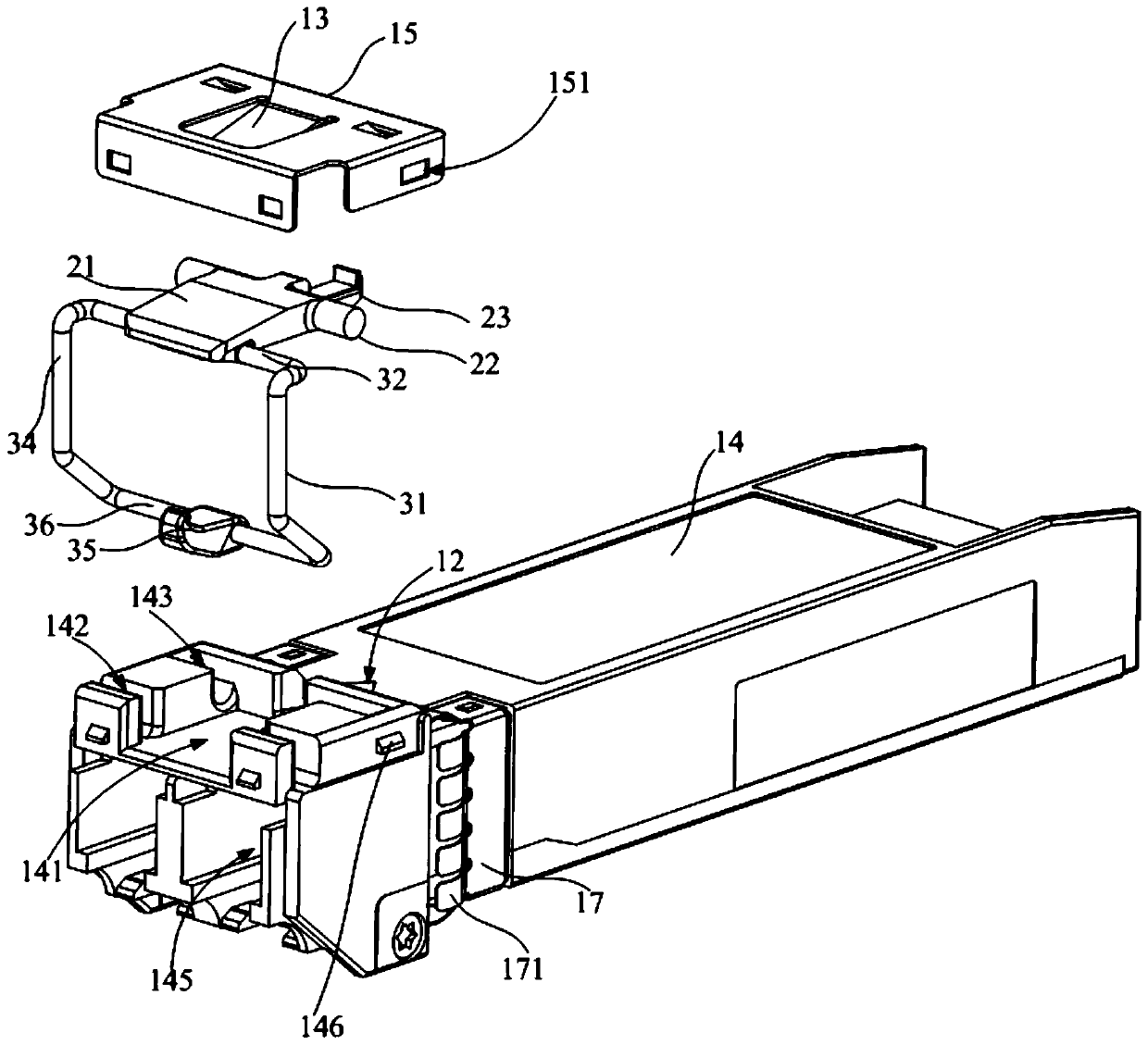
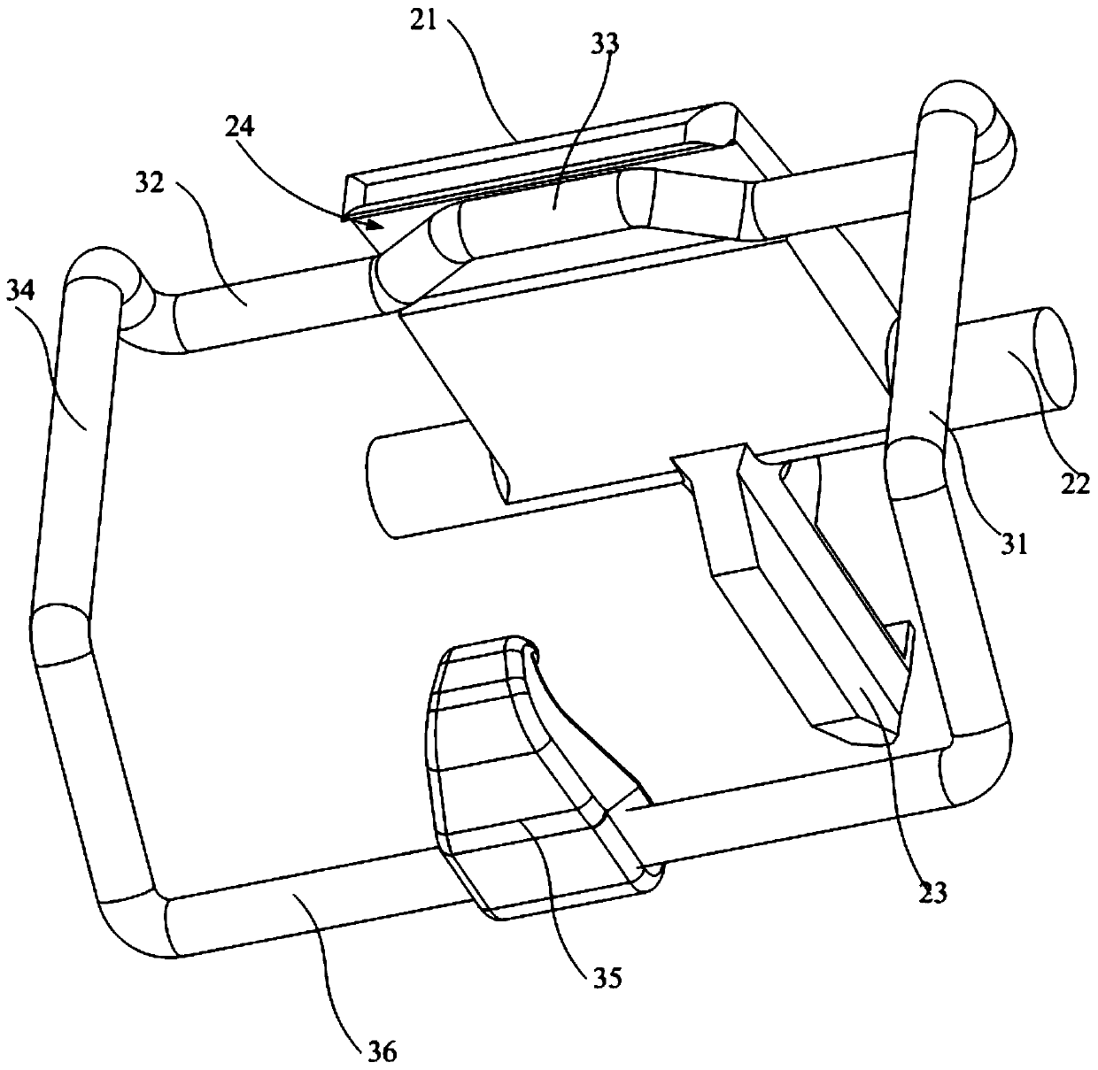
Unlocking structure and optical module

A technology for unlocking and locking blocks, which is applied in the direction of light guides, optics, optical components, etc., and can solve problems such as limited service life of springs and locking blocks, complex installation structures of springs and locking blocks, and inconvenient unlocking

Pending Publication Date: 2020-06-26
APAT OPTOELECTRONICS COMPONENTS
View PDF0 Cites 0 Cited by
  • Summary
  • Abstract
  • Description
  • Claims
  • Application Information

AI Technical Summary

Problems solved by technology

When using the optical module, insert it into the metal cage of the optical communication equipment and lock the optical module; commonly, the optical module is locked to the optical module through the locking block and the spring. In the metal cage, but the service life of the spring and the lock block is limited, and the installation structure of the spring and the lock block is complicated, and it is inconvenient to unlock

Method used


Image

  • Unlocking structure and optical module
  • Unlocking structure and optical module
  • Unlocking structure and optical module

Examples


Embodiment Construction

[0039] The following will clearly and completely describe the technical solutions in the embodiments of the present invention with reference to the accompanying drawings in the embodiments of the present invention. Obviously, the described embodiments are only part of the embodiments of the present invention, not all of them. Based on the embodiments of the present invention, all other embodiments obtained by persons of ordinary skill in the art without creative efforts fall within the protection scope of the present invention.

[0040] It should be noted that if there is a directional indication (such as up, down, left, right, front, back...) in the embodiment of the present invention, the directional indication is only used to explain the position in a certain posture (as shown in the accompanying drawing). If the specific posture changes, the directional indication will also change accordingly.

[0041] In addition, if there are descriptions involving "first", "second" and ...


PUM


Abstract

The invention discloses an unlocking structure and an optical module. The unlocking structure comprises a base, a locking piece and a rotating piece. The base is provided with a containing cavity anda locking groove communicated with the containing cavity; the base is provided with an elastic piece arranged by corresponding to the containing cavity; the locking piece comprises a pressing plate, arotating shaft and a locking block which are connected in sequence, the pressing plate and the locking block are rotatably arranged on the base through the rotating shaft, the pressing plate is arranged in the containing cavity, the locking block is arranged in the locking groove, and the pressing plate is abutted against the elastic piece; the rotating piece is arranged on the base in a rotatable mode. According to the unlocking structure, the structure of the optical module is simplified and the efficiency of plugging and unplugging the optical module is improved.

Description

technical field [0001] The invention relates to the technical field of photoelectric conversion equipment, in particular to an unlocking structure and an optical module using the unlocking structure. Background technique [0002] The optical module is an important device in optical communication equipment. It is used for photoelectric conversion, so that the electrical signal is converted into an optical signal and propagated in the form of light in the optical device. The optical signal in the optical device can also be converted into an electrical signal, which is used by the signal device Received. When using the optical module, insert it into the metal cage of the optical communication equipment and lock the optical module; commonly, the optical module is locked to the optical module through the locking block and the spring. However, the service life of the spring and the lock block is limited, and the installation structure of the spring and the lock block is complicat...

Claims


Application Information

Patent Timeline
Patent Type & Authority Applications(China)
IPC IPC(8): G02B6/42
CPCG02B6/4261
Inventor 庄礼杰易贤
Owner APAT OPTOELECTRONICS COMPONENTS
Why Eureka
Try Eureka