Astronaut low-gravity motion simulation exoskeleton

A technology of motion simulation and exoskeleton, which is applied to the simulation device, simulator, transportation and packaging of space navigation conditions, and can solve the problems of short time, high simulation cost, and short tower drop simulation time

Active Publication Date: 2020-06-26
XI AN JIAOTONG UNIV
View PDF7 Cites 20 Cited by
  • Summary
  • Abstract
  • Description
  • Claims
  • Application Information

AI Technical Summary

Problems solved by technology

The analysis of the existing low-gravity simulation technology shows that the parabolic weightless flight of the aircraft can produce a realistic zero-gravity acceleration environment, but because of its short duration (15-45s), the simulation cost is huge, and it can only be used by astronauts. Weightlessness experience and simple movement training; the simulation time of falling tower is short (2-10s); due to the dynamic damping and viscous effect of water in the neutral buoyancy pool, the astronauts should not move too fast in the tank (≤0.5m /s), otherwise the resistance of the fluid will seriously distort the weightlessness effect; the air-floor table can realize the low-gravity environment simulation of two-dimensional translation, but it is difficult to realize the complex motion simulation in three-dimensional space; virtual reality technology is mainly in the aspects of vision and local force feedback Simulation cannot fully simulate the feeling of the human body in a low-gravity environment, and generally needs to be combined with other physical simulation methods; the existing suspension gravity compensation system, such as the partial gravity simulator (Practical Gravity Simulator, POGO) and Active Response Gravity Offload System (Active Response Gravity Offload System, ARGOS), although they can passively or even actively compensate the gravity of the human body, at this time the human body’s elbows, shoulders, waist, hips, k

Method used


Image

  • Astronaut low-gravity motion simulation exoskeleton
  • Astronaut low-gravity motion simulation exoskeleton
  • Astronaut low-gravity motion simulation exoskeleton

Examples


Embodiment Construction

[0039] The present invention will be described in further detail below in conjunction with the accompanying drawings.

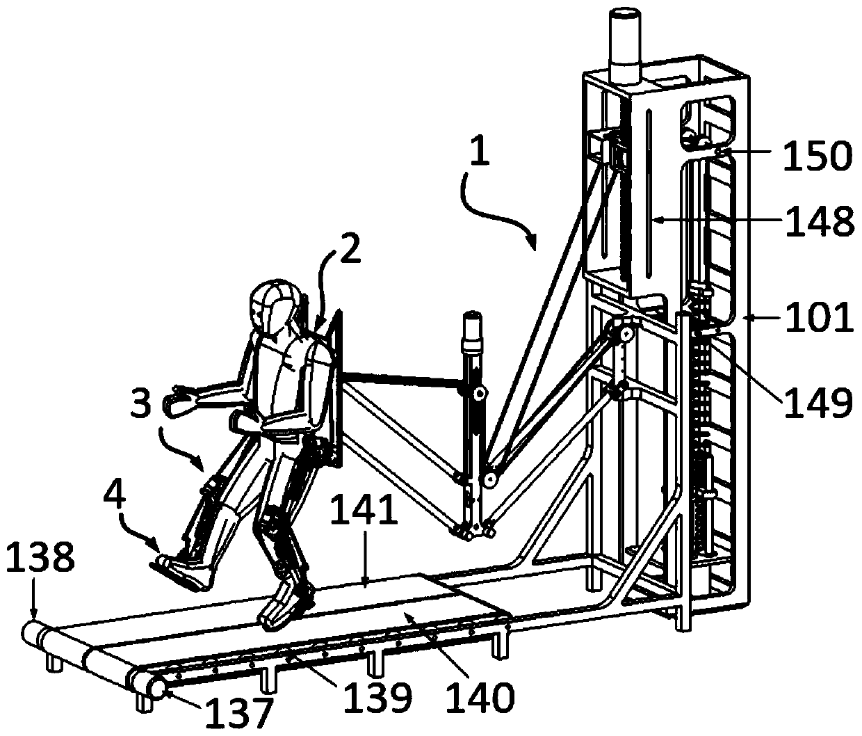
[0040] like figure 1 Shown: This invention patent is designed for a low-gravity movement simulation exoskeleton overall system for astronauts, including 1 overall gravity balance mechanism, 2 exoskeleton back balance mechanism, 3 exoskeleton legs, 4 exoskeleton feet, a total of four parts, such as figure 1 shown.

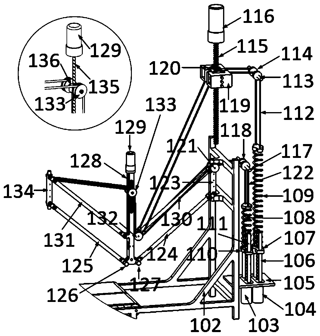
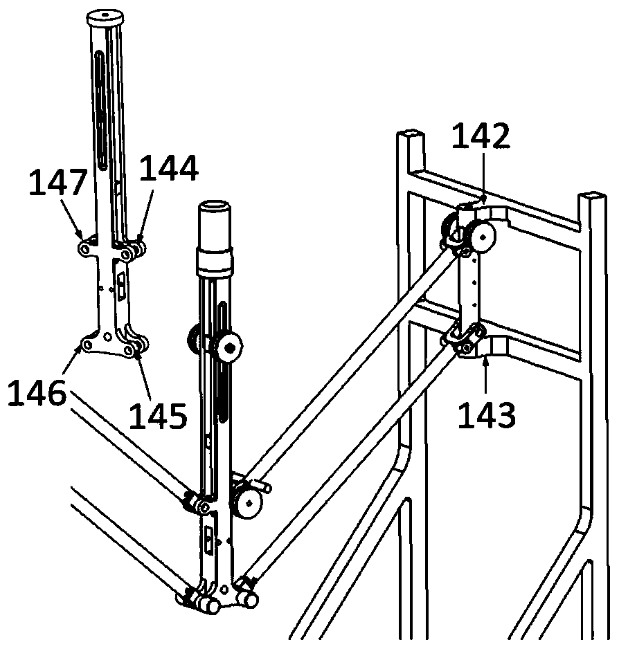
[0041] like figure 2 image 3 As shown: the whole system is supported by the bracket base 102, the vertical frame 101 is fixed on the back of the bracket base 102, the linear motor 1 103 and the linear motor 2 104 are fixedly connected to the bottom of the bracket base 102 through the balance motor bracket 105, and the balance motor bracket There are screw rod optical axis one 111 and screw rod optical axis two 106 on 105, slide block two 107 is connected with the nut of linear motor two 104, and can slide on screw rod optical axis 106; Slide ...


PUM


Abstract

An astronaut low-gravity motion simulation exoskeleton comprises an overall gravity balance mechanism, an exoskeleton back balance mechanism is arranged on the overall gravity balance mechanism, and the two sides of the lower end of the exoskeleton back balance mechanism are connected with exoskeleton feet through exoskeleton legs. A parallelogram spring gravity compensation mechanism exists in the exoskeleton between the base and the lower limbs, and the gravity can be compensated in real time according to different wearers and different motion states. The exoskeleton parts of the lower limbsof the human body adopt parallelogram spring mechanisms connected in parallel to balance the gravity of the legs, and the series elastic drivers of the hip joints and the knee joints enable the exoskeleton parts of the human body to flexibly follow in the movement process and actively balance the gravity of the legs in real time. Accurate force control is achieved under the condition that large gravity loads are transmitted, flexible following movement is achieved, and the comfort of a wearer is improved.

Description

technical field [0001] The invention relates to the technical field of a space low-gravity training system on the surface of the earth, in particular to an astronaut low-gravity exercise simulation exoskeleton. Background technique [0002] Low-gravity environment simulation technology is the most important technology to help astronauts conduct low-gravity training on the earth. Space powers such as the United States, Russia, and China have developed weightless flight, drop towers, neutral buoyancy pools, air bearing tables, and virtual reality. technology, suspended gravity compensation system and other low-gravity environment simulation technologies. The analysis of the existing low-gravity simulation technology shows that the parabolic weightless flight of the aircraft can produce a realistic zero-gravity acceleration environment, but because of its short duration (15-45s), the simulation cost is huge, and it can only be used by astronauts. Weightlessness experience and ...

Claims


Application Information

Patent Timeline
IPC IPC(8): G09B9/00B25J9/00
CPCB25J9/00B25J9/0006G09B9/00
Inventor 朱爱斌宋纪元屠尧
Owner XI AN JIAOTONG UNIV
Why Eureka
Try Eureka