
Circuit breaker

A technology for circuit breakers and moving contacts, applied in circuits, parts of protection switches, electrical components, etc., can solve the problems of the coil of the circuit breaker being burned out, affecting the reliability of the circuit breaker, and the slow breaking speed of the breakpoint, etc. Achieve the effect of improving reliability, simple structure, and improving action speed

Pending Publication Date: 2020-06-26
ZHEJIANG CHINT ELECTRIC CO LTD
View PDF0 Cites 2 Cited by
  • Summary
  • Abstract
  • Description
  • Claims
  • Application Information

AI Technical Summary

Problems solved by technology

[0002] The test mechanism of the circuit breaker is limited by the space of the housing. The test circuit of the test mechanism usually adopts a single break point structure. There is a voltage to the ground due to conduction, which may cause the risk of electric shock during use, and does not meet the safety regulations of specific areas. One of the breakpoints is controlled by the handle, and the test circuit will be turned on when the test button is pressed when the handle is closed, but the breakpoint conduction and disconnection speeds are affected by the closing and opening speeds of the handle. The problem of reset will cause the breakpoint to disconnect slowly. At this time, if the circuit breaker is reversed, pressing the test button will cause the test circuit to disconnect slowly, causing the coil of the circuit breaker to heat up and burn, and the problem of circuit breaker failure is serious. Affect the reliability of the circuit breaker

Method used


Image

  • Circuit breaker
  • Circuit breaker
  • Circuit breaker

Examples


Embodiment Construction

[0046] The following is attached Figures 1 to 18 The given examples further illustrate the specific implementation of the circuit breaker created by the present invention. The circuit breaker created by the present invention is not limited to the description of the following embodiments.

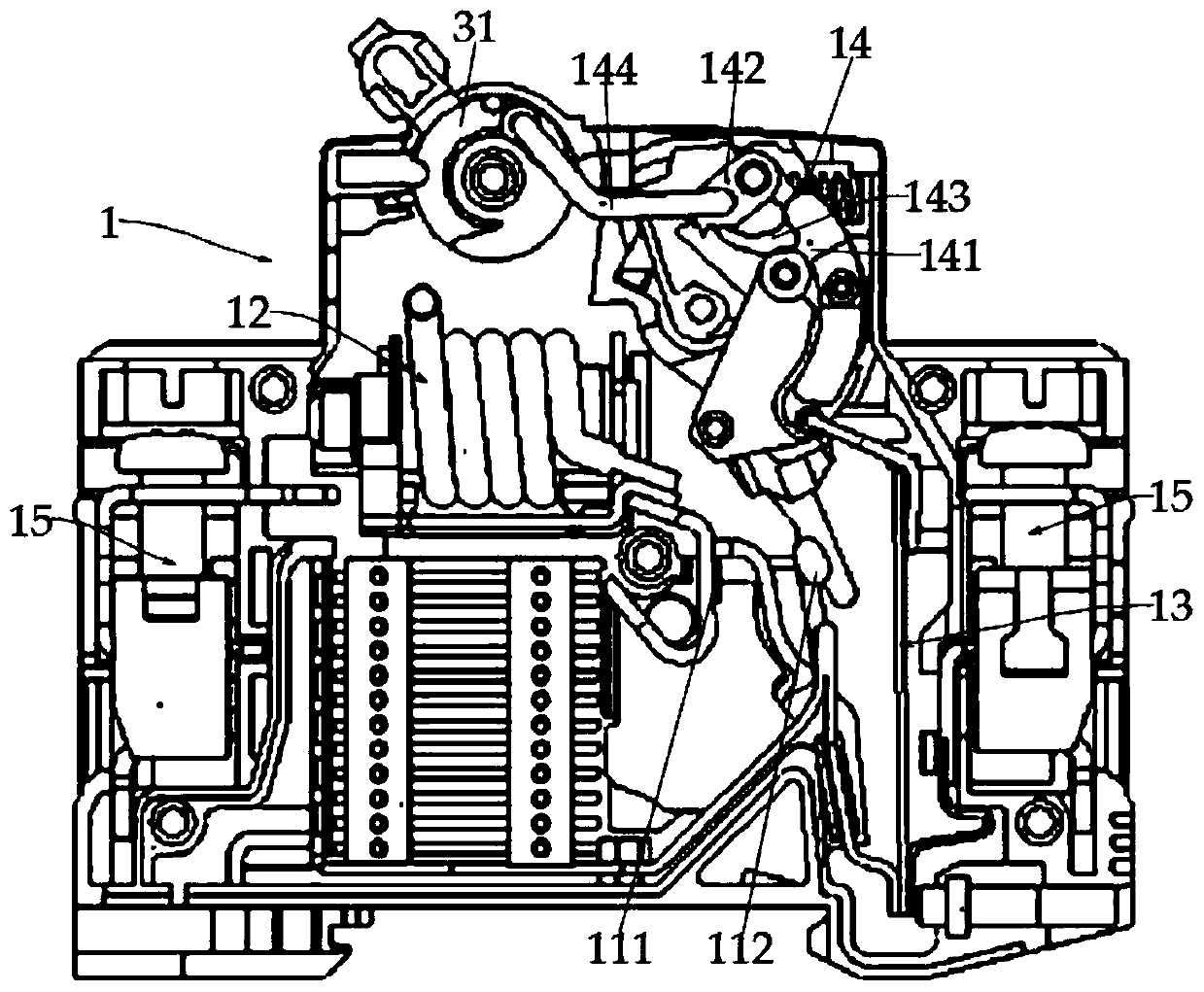
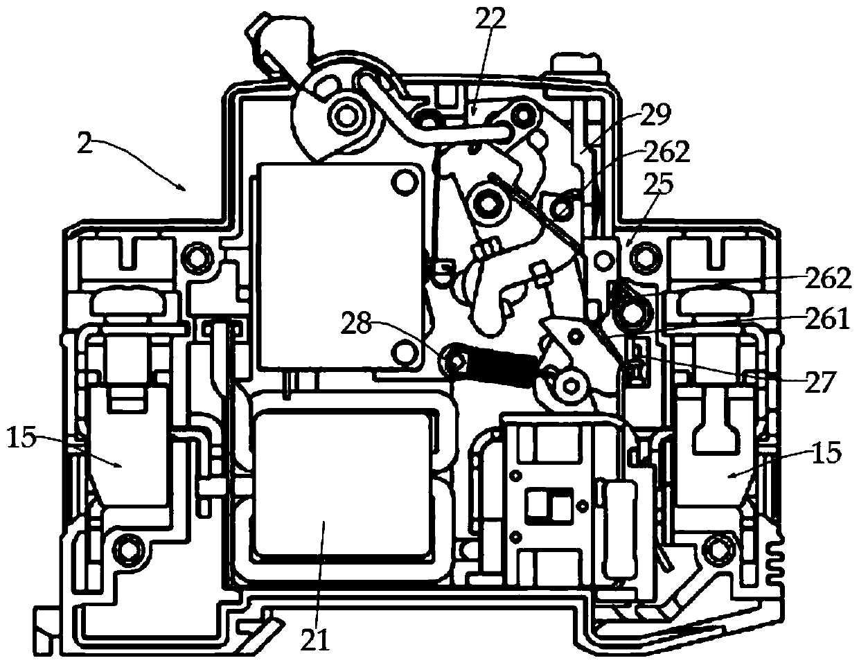
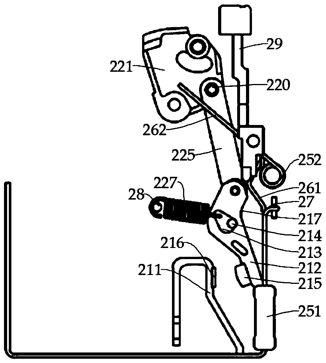
[0047] Such as Figure 1-2 As shown, the circuit breaker created by the present invention includes a casing and a circuit breaker phase pole 1 and a leakage protection pole 2 arranged side by side on both sides of the casing, and a partition 32 is provided between the circuit breaker phase pole 1 and the leakage protection pole 2 , the phase pole 1 of the circuit breaker includes a static contact 111 and a moving contact 112 that are oppositely arranged and connected to the circuit respectively. The moving contact 112 is installed on the phase pole operating mechanism 14 to swing and cooperate with the static contact 111. 2 Including zero-sequence current transformer 21, leakage operating...


PUM


Abstract

A circuit breaker comprises a shell, and a circuit breaker phase electrode and an electric leakage protection electrode which are arranged on two sides of the shell side by side. The circuit breaker is characterized in that the electric leakage protection electrode comprises a zero sequence current transformer, an electric leakage operation mechanism, an electric leakage test mechanism, a neutralpole static contact and a neutral pole moving contact which are oppositely arranged in the shell; the circuit breaker phase pole comprises a phase pole operating mechanism, a static contact and a moving contact which are oppositely arranged, wherein the moving contact is connected with the phase pole operating mechanism; the main loop of the phase pole of the circuit breaker passes through the zero sequence current transformer; the test mechanism forms a test loop with double breakpoints through two contacts of a first contact part and a second contact part on the elastic part; moreover, the first contact part is driven by the neutral line driving part connected with the neutral pole moving contact to be contacted with the first contact part, and the neutral line driving part is connectedwith the phase pole operating mechanism or the electric leakage operating mechanism, so the test button can be pressed down to disconnect the test loop when the phase pole of the circuit breaker is switched off, and the reliability of the circuit breaker is improved.

Description

technical field [0001] The invention relates to the field of low-voltage electrical appliances, in particular to a circuit breaker. Background technique [0002] The test mechanism of the circuit breaker is limited by the space of the housing. The test circuit of the test mechanism usually adopts a single break point structure. There is a voltage to the ground due to conduction, which may cause the risk of electric shock during use, and does not meet the safety regulations of specific areas. One of the breakpoints is controlled by the handle, and the test circuit will be turned on when the test button is pressed when the handle is closed, but the breakpoint conduction and disconnection speeds are affected by the closing and opening speeds of the handle. The problem of reset will cause the breakpoint to disconnect slowly. At this time, if the circuit breaker is reversed, pressing the test button will cause the test circuit to disconnect slowly, causing the coil of the circui...

Claims


Application Information

Patent Timeline
IPC IPC(8): H01H71/24H01H71/12H01H83/14
CPCH01H71/24H01H71/128H01H83/14
Inventor 刘瑾朱俊李罗斌吴正威
Owner ZHEJIANG CHINT ELECTRIC CO LTD
Learn More