A micro-track vehicle and its running device

A traveling device and vehicle technology, applied in the field of rail vehicles, can solve the problem that micro-rail vehicles can only travel in one direction, and achieve the effects of reducing weight and increasing traction

Active Publication Date: 2021-07-27
CRRC TANGSHAN CO LTD
View PDF9 Cites 0 Cited by
  • Summary
  • Abstract
  • Description
  • Claims
  • Application Information

AI Technical Summary

Problems solved by technology

However, current microrail vehicles can only travel in one direction

Method used


Image

  • A micro-track vehicle and its running device
  • A micro-track vehicle and its running device
  • A micro-track vehicle and its running device

Examples


Embodiment 1

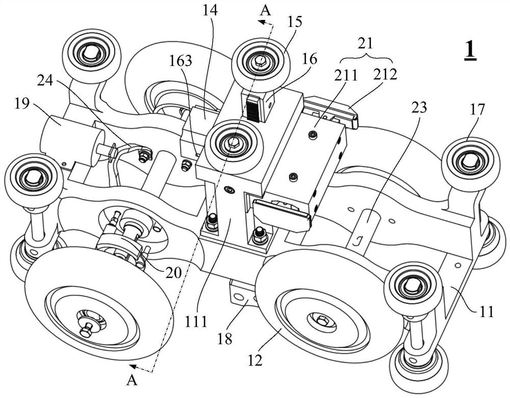
[0035] The embodiment of the present application provides a walking device 1, such as figure 1 and figure 2 As shown in the structure, the running device 1 includes:

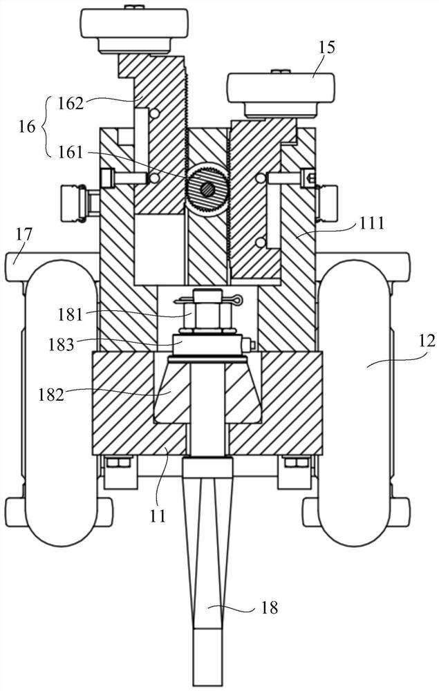
[0036] Frame 11, a column 111 is installed at the center of the top of the frame 11, and a carriage hanger 18 is installed at the bottom of the frame 11. At least a part of the carriage hanger 18 protrudes from the bottom of the frame 11, and the protruding part is used for hoisting the micro frame. The carriage of the rail vehicle; in order to reduce the weight of the running device 1 without reducing the structural strength and rigidity of the frame 11, the frame 11 can be made of aluminum alloy material;

[0037] Four driving wheels 12, the four driving wheels 12 are symmetrically installed on both sides of the frame 11; such as figure 1 As shown in the structure, two front and rear driving wheels 12 are arranged on one side of the vehicle frame 11 , and two front and rear driving wheels 12 are arranged on...

Embodiment 2

[0059] The embodiment of the present application provides a micro-rail vehicle, the micro-rail vehicle includes a carriage and any one of the running devices 1 provided in the above embodiments, and the carriage is hoisted at the bottom of the carriage hanger 18 .

[0060] The specific working process of the micro-rail vehicle using the above-mentioned running device 1 is as follows:

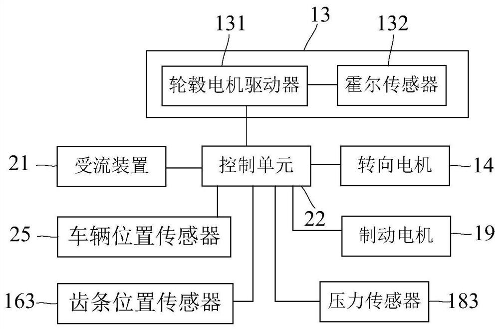
[0061] The start-up process control of the micro-rail vehicle: the control unit 22 judges the start-up conditions of the micro-rail vehicle according to the various signals collected, and transmits the start-up speed regulation command signal to the in-wheel motor driver 131 of the four in-wheel motors 13, and through the in-wheel motor driver 131 controls the operation of each in-wheel motor 13 . The Hall sensor 132 located in the in-wheel motor 13 detects the running state of the in-wheel motor 13 in real time and outputs it to the in-wheel motor driver 131. The in-wheel motor driver 131 makes...


PUM


Abstract

The embodiments of the present application relate to the technical field of rail vehicles, and in particular, to a micro-rail vehicle and a running device thereof. The running device includes the frame, four driving wheels, four wheel hub motors, steering motor, four pairs of guide wheels, carriage suspension, brake motor, current receiving device and control unit; the wheel hub motors correspond to the driving wheels one by one, and use To drive the drive wheel to rotate; the steering motor is installed on one side of the column, and the steering motor and the two steering stable wheels are connected through a transmission mechanism to drive the two steering stable wheels to move in the vertical direction; the brake motor It is used to drive the brake pads installed on the frame to brake the driving wheels; the current receiving device is used to provide electric energy to the hub motor, brake motor and control unit; the control unit is used to control the hub motor, brake motor and steering Motor start and stop. The running device can realize four-wheel independent driving through one-to-one corresponding driving wheels and hub motors, and can realize two-way driving.

Description

technical field [0001] The present application relates to the technical field of rail vehicles, and in particular, to a micro-rail vehicle and a running device thereof. Background technique [0002] Micro-rail vehicle is a new mode of transportation with small volume, point-to-point, customized, fully automatic and unmanned driving. The running gear of the micro-rail vehicle runs inside or above the rail beam. However, current micro-rail vehicles can only travel in one direction. SUMMARY OF THE INVENTION [0003] The embodiments of the present application provide a micro-rail vehicle and its running device. The running device can realize four-wheel independent driving through one-to-one corresponding driving wheels and in-wheel motors. Therefore, the running device can realize bidirectional running. [0004] According to a first aspect of the embodiments of the present application, a walking device is provided, comprising: [0005] a frame, a column is installed at the ...

Claims


Application Information

Patent Timeline
Patent Type & Authority Patents(China)
IPC IPC(8): B60K7/00B62D5/04
CPCB60K7/0007B62D5/0457
Inventor 李化明秦佳颖杜群威刘政曹科宇王东星陈磊司丽方培嫘王宏图
Owner CRRC TANGSHAN CO LTD
Why Eureka
Try Eureka