An electro-hydraulic braking system and a method for preventing wheels of a vehicle from slipping by using the electro-hydraulic braking system

A technology of electro-hydraulic brakes and wheels, which is applied in the direction of braking action starting devices, brakes, brake components, etc., and can solve problems such as vehicle instability

Active Publication Date: 2020-06-30
BWI (SHANGHAI) CO LTD
View PDF19 Cites 3 Cited by
  • Summary
  • Abstract
  • Description
  • Claims
  • Application Information

AI Technical Summary

Problems solved by technology

This feature can easily lock the rear wheels, making the vehicle unstable

Method used


Image

  • An electro-hydraulic braking system and a method for preventing wheels of a vehicle from slipping by using the electro-hydraulic braking system
  • An electro-hydraulic braking system and a method for preventing wheels of a vehicle from slipping by using the electro-hydraulic braking system
  • An electro-hydraulic braking system and a method for preventing wheels of a vehicle from slipping by using the electro-hydraulic braking system

Examples


Embodiment Construction

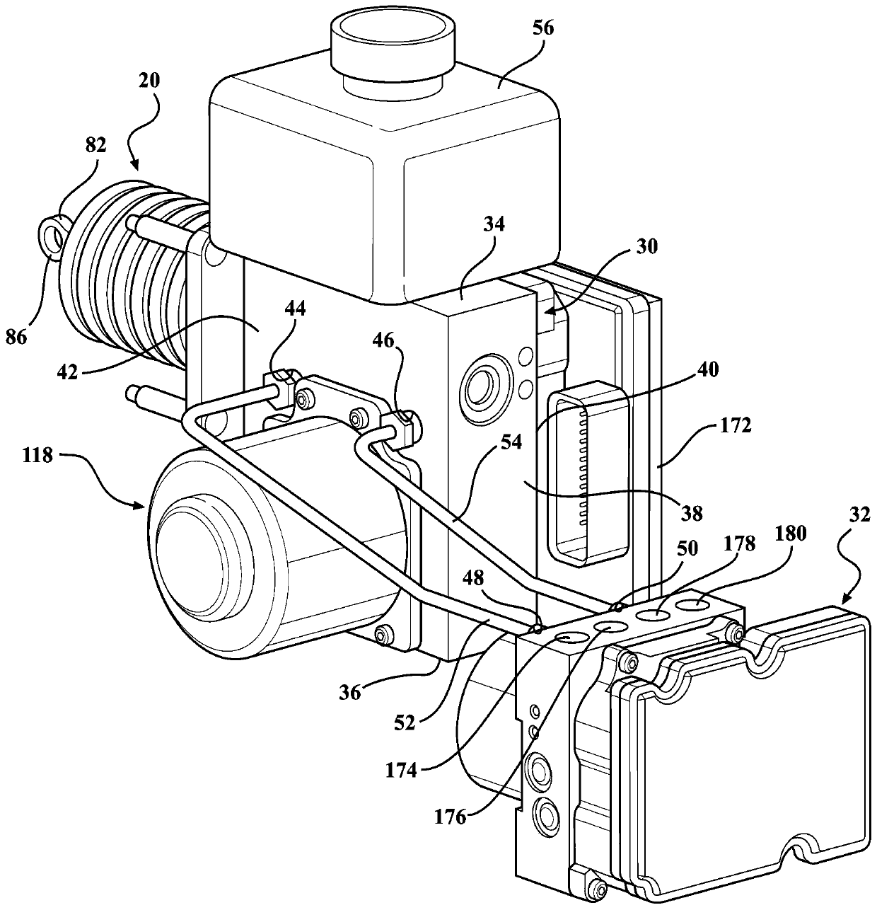
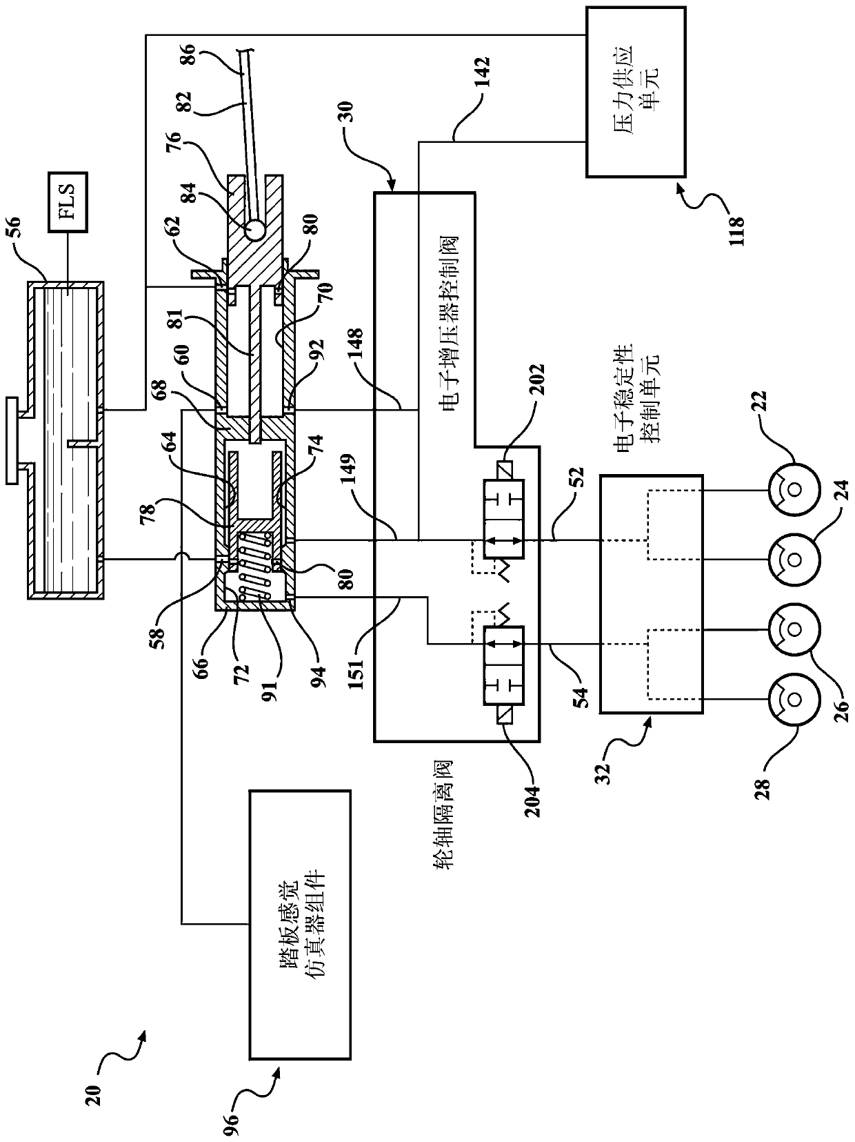
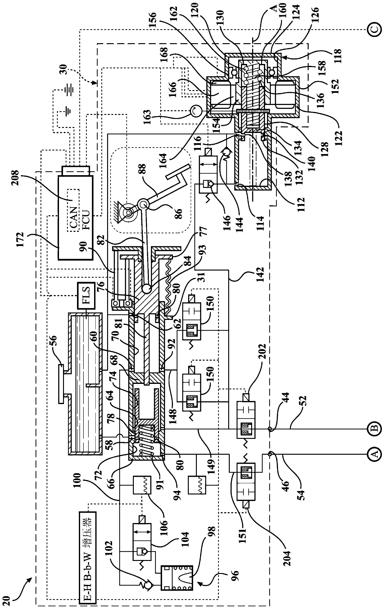
[0023] Referring to the drawings, wherein like reference numerals indicate corresponding parts throughout the several views, figure 1 An electrohydraulic braking system 20 constructed in accordance with one embodiment of the present invention is generally shown. Typically, the electrohydraulic braking system 20 may be implemented in an automobile having four wheel brakes 22, 24, 26, 28 comprising a pair of front wheel brakes parts 22, 24 and a pair of rear wheel brake parts 26, 28.

[0024] refer to figure 1 , the electrohydraulic braking system 20 is a two-tank system including a master cylinder 30 in fluid communication with a manifold block 32 . The master cylinder 30 having a generally rectangular shape includes a plurality of surfaces including a top surface 34 , a bottom surface 36 , a pair of side surfaces 38 , a front surface 40 and a rear surface 42 . The top surface 34 and the bottom surface 36 are opposite and spaced apart from each other. Side surfaces 38 oppos...


PUM


Abstract

The invention provides an electro-hydraulic braking system and a method for preventing wheels of a vehicle from slipping by using the electro-hydraulic braking system. An electro-hydraulic brake system includes a master cylinder in fluid communication with a reservoir tank containing brake fluid. The master cylinder defines a bore and primary and secondary openings. The protrusion extends outwardly from a rear surface of the master cylinder. A pressure supply unit is coupled to a front surface of the master cylinder and is in fluid communication with a reservoir tank to supply brake fluid therefrom. A master cylinder electronic control unit is coupled to the rear surface and in abutting relationship with the protrusion. At least one isolation valve is disposed on the rear surface, spaced apart from the protrusion, and received by the master cylinder electronic control unit to adjust a brake fluid flow from the master cylinder to the wheel brake.

Description

technical field [0001] The present invention generally relates to an electrohydraulic braking system for a vehicle and a method of controlling an isolation valve of the electrohydraulic braking system. Background technique [0002] As electric and hybrid vehicles continue to proliferate in markets around the world, it is known that by utilizing the motor-generator output capability of the device during braking, significant battery life extensions can be obtained. However, the input torque in generator mode used to recharge the battery does not coincide with the driver input function of pedal effort / travel versus vehicle deceleration. In order to implement this complex function, the vehicle's hydraulic brakes must supply the difference between the generator braking torque and the braking torque requested by the driver. [0003] The need for what is commonly referred to as regenerative braking blending has been understood by the engineering community for many years. One of t...

Claims


Application Information

Patent Timeline
Patent Type & Authority Applications(China)
IPC IPC(8): B60T13/68B60T8/40
CPCB60T13/686B60T8/4081B60T7/042B60T15/045B60T8/343B60T8/36B60T13/745
Inventor D·F·罗伊特P·夏美特
Owner BWI (SHANGHAI) CO LTD
Why Eureka
Try Eureka