Charging method using wind energy for power generation
A charging method and wind energy power generation technology, applied in the direction of wind energy power generation, wind turbine, wind turbine combination, etc., can solve problems such as environmental impact, and achieve the effect of protecting the environment, realizing recycling, and realizing rapid use.
- Summary
- Abstract
- Description
- Claims
- Application Information
AI Technical Summary
Problems solved by technology
Method used
Image

Examples
Embodiment Construction
[0034] The following will clearly and completely describe the technical solutions in the embodiments of the present invention with reference to the accompanying drawings in the embodiments of the present invention. Obviously, the described embodiments are only some, not all, embodiments of the present invention. Based on the embodiments of the present invention, all other embodiments obtained by persons of ordinary skill in the art without making creative efforts belong to the protection scope of the present invention.
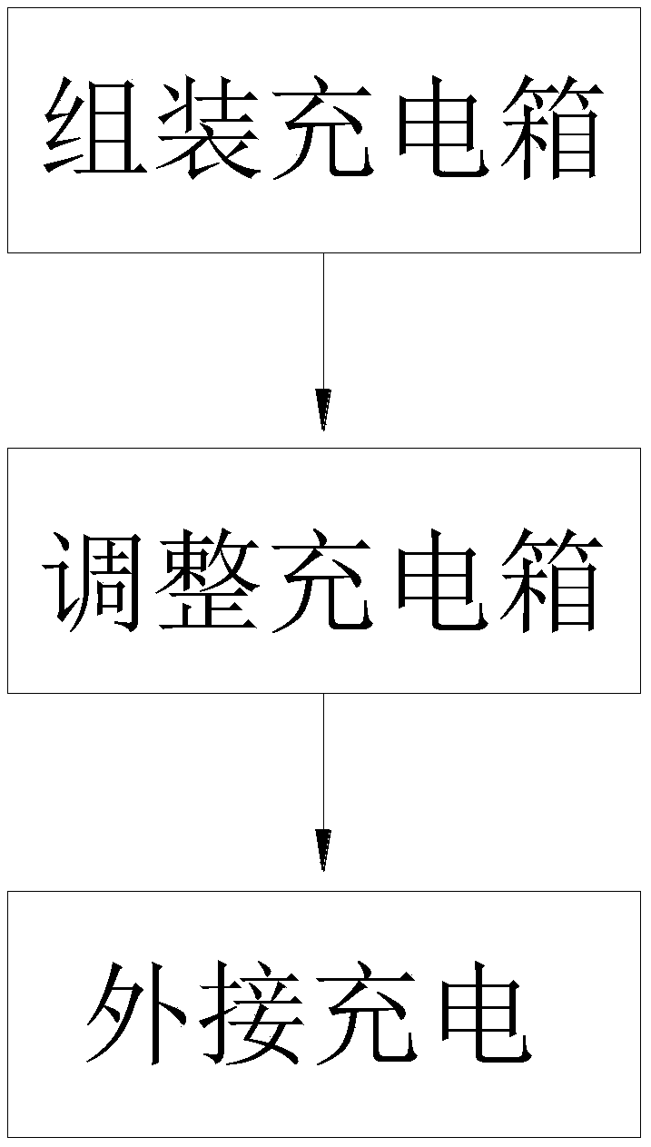
[0035] Specific examples Figure 1-5 Described, a kind of charging method using wind energy to generate electricity, described charging method comprises the following steps:
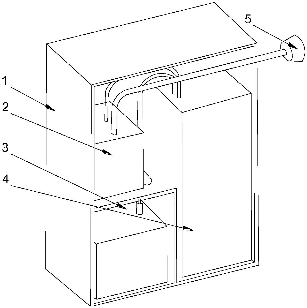
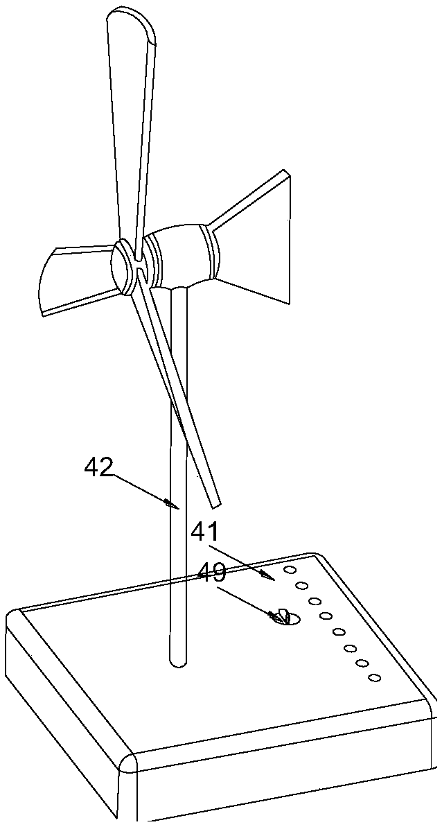
[0036] 1) Assemble the charging box 1, and install the AC transformer 2, the DC transformer 3 and a wind energy converter 4 in the charging box 1;
[0037] 2) Adjust the position of the wires in the charging box 1, and arrange the wires on the DC transformer 3, the AC transformer 2 and ...
PUM
 Abstract
Description
Claims
Application Information
 - Generate Ideas
- Intellectual Property
- Life Sciences
- Materials
- Tech Scout
- Unparalleled Data Quality
- Higher Quality Content
- 60% Fewer Hallucinations
Browse by: Latest US Patents, China's latest patents, Technical Efficacy Thesaurus, Application Domain, Technology Topic, Popular Technical Reports.
© 2025 PatSnap. All rights reserved.Legal|Privacy policy|Modern Slavery Act Transparency Statement|Sitemap|About US| Contact US: help@patsnap.com