Enhanced synchronous belt

A synchronous belt, enhanced technology, applied in the field of transmission, can solve the problems of weak adhesion, weak shear resistance, tearing, etc., to reduce labor costs and material costs, increase the shear strength of the tooth layer, and increase the belt body strength and effect

Pending Publication Date: 2020-06-30
邝立辉
View PDF0 Cites 0 Cited by
  • Summary
  • Abstract
  • Description
  • Claims
  • Application Information

AI Technical Summary

Problems solved by technology

[0004] Common synchronous belts have the following defects: 1. The bonding between the core wire layer and the tooth layer and the belt body layer is not firm, and it is easy for the tooth layer and the belt body layer to be stripped of the core wire layer and torn off; 2. The synchronous belt The tooth root part of the tooth layer is not firmly bonded and has weak shear resistance, resulting in the phenomenon that the synchronous belt teeth are scraped off by the synchronous gear teeth

Method used


Image

  • Enhanced synchronous belt
  • Enhanced synchronous belt
  • Enhanced synchronous belt

Examples


Embodiment 1

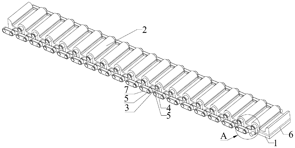
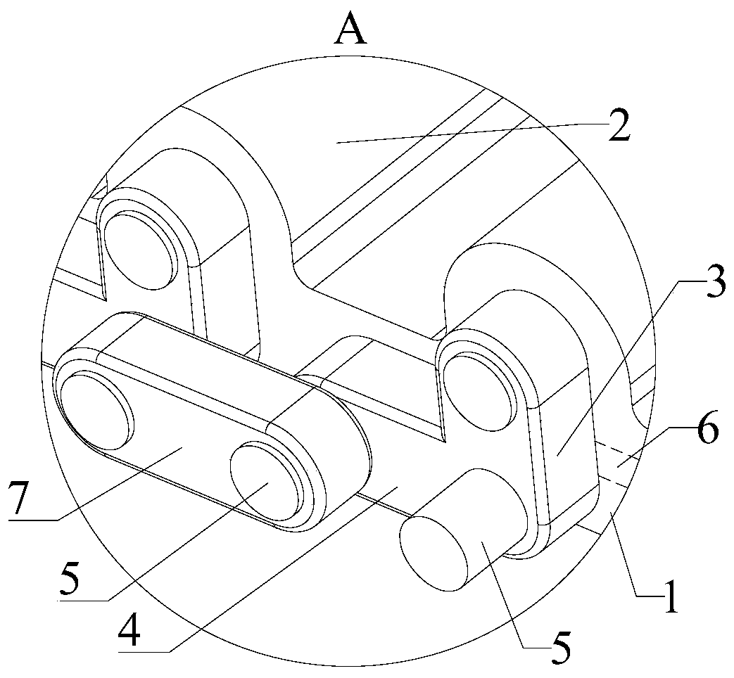
[0036] Please refer to figure 1 with figure 2 , Embodiment 1 of the present invention is: an enhanced synchronous belt, which can be used in the fields of mechanical transmission, robot transmission, electromechanical product transmission, sports product transmission and other transmission fields.

[0037] The reinforced synchronous belt includes a belt body layer 1, the inner side of the belt body layer 1 is provided with a tooth layer 2, and also includes a reinforcement unit, and the reinforcement unit includes a first connecting piece 3, which is arranged in the tooth layer 2 The first shaft 4 and the second shaft 5 arranged on the body layer 1, the first shaft 4 and the second shaft 5 are respectively connected in rotation with the first connecting member 3.

[0038] The body layer 1 is embedded with a core layer 6 , preferably, the second axis 5 is located on a side of the core layer 6 away from the tooth layer 2 .

[0039] In order to balance the force of the timing ...

Embodiment 2

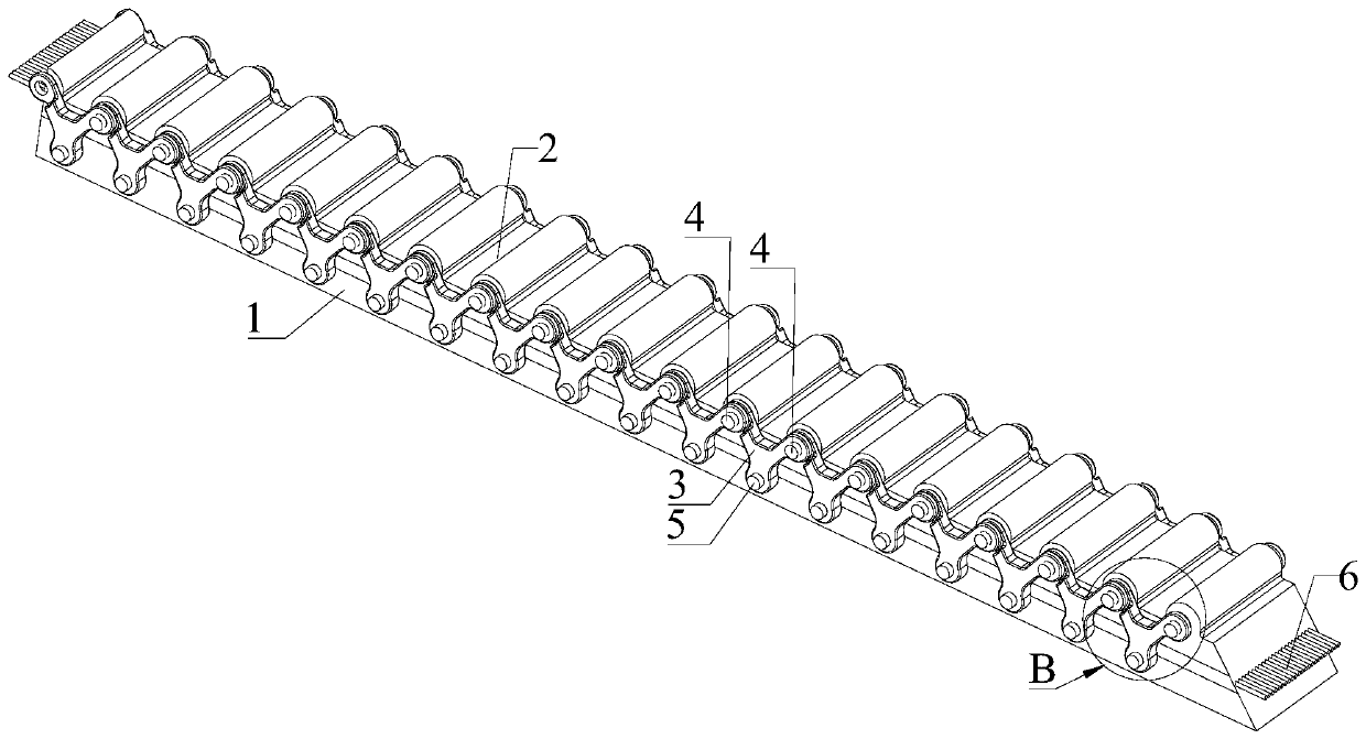
[0045] Please refer to image 3 with Figure 4 , Embodiment 2 of the present invention is a modification proposed on the basis of Embodiment 1. The difference from Embodiment 1 is:

[0046] In the reinforcing unit of the reinforced synchronous belt in this embodiment, the number of the first shaft 4 and the second shaft 5 is one respectively, the first connecting member 3 is V-shaped or Y-shaped, and the second shaft 4 is V-shaped or Y-shaped. A connecting piece 3 is also rotatably connected to the first shaft 4 in another adjacent reinforcement unit. It is easy to understand that the V-shaped or Y-shaped first connecting member 3 can be an integral structure, or a spliced ​​structure formed by splicing a plurality of connecting rods.

[0047] Further, the distance between the first shaft 4 and the second shaft 5 in the reinforcement unit is equal to the distance between the second shaft 5 and the first shaft 4 in another adjacent reinforcement unit .

[0048] To sum up, com...


PUM


Abstract

The invention discloses an enhanced synchronous belt which comprises a belt body layer, wherein a tooth layer is arranged on the inner side of the belt body layer. The enhanced synchronous belt further comprises an enhancing unit which comprises a first connecting part, a first shaft arranged in the tooth layer and a second shaft arranged on the belt body layer. The first shaft and the second shaft are connected to the first connecting part, separately. In the enhanced synchronous belt, the enhancing unit can fix the tooth layer to the belt body tightly to enhance the strength of the belt bodyof the synchronous belt and the shearing strength of the tooth layer, so that the service life of the synchronous belt is prolonged effectively and the labor cost and the material cost caused by replacing the synchronous belt frequently are lowered.

Description

technical field [0001] The invention relates to the technical field of transmission, in particular to an enhanced synchronous belt. Background technique [0002] Synchronous belt transmission is a flexible transmission solution with high flexibility, accurate positioning and low noise. [0003] A common synchronous belt usually includes a belt body layer, a tooth layer and a core wire layer embedded in the belt body layer. The role of the strength of the timing belt; the belt body layer plays the role of fixing the tooth layer and the core wire layer. [0004] Common synchronous belts have the following defects: 1. The bonding between the core wire layer and the tooth layer and the belt body layer is not firm, and it is easy for the tooth layer and the belt body layer to be stripped of the core wire layer and torn off; 2. The synchronous belt The tooth root part of the tooth layer is not firmly bonded and has weak shear resistance, resulting in the phenomenon that the sync...

Claims


Application Information

Patent Timeline
Patent Type & Authority Applications(China)
IPC IPC(8): F16G1/28F16G1/18
CPCF16G1/18F16G1/28
Inventor 不公告发明人
Owner 邝立辉
Why Eureka
Try Eureka