Support structure for LED street lamp
A technology of LED street lamps and support structures, applied in lighting devices, outdoor lighting, light sources, etc., can solve the problems of potential safety hazards, swing distance of street lamps and arc poles, separation from street lamp poles, etc., to achieve increased stability, good support, The effect of ensuring stability
- Summary
- Abstract
- Description
- Claims
- Application Information
AI Technical Summary
Problems solved by technology
Method used
Image

Examples
Embodiment Construction
[0020] The following will clearly and completely describe the technical solutions in the embodiments of the present invention with reference to the accompanying drawings in the embodiments of the present invention. Obviously, the described embodiments are only some, not all, embodiments of the present invention.
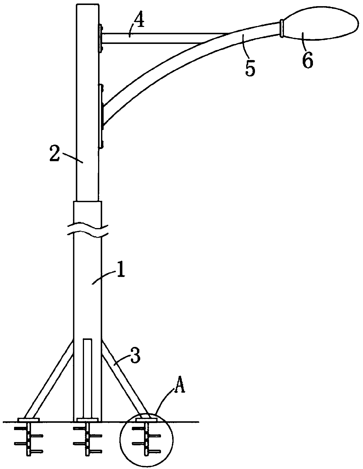
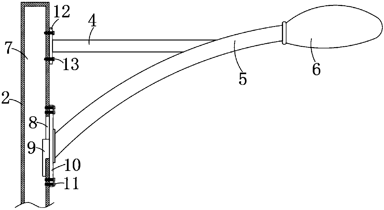
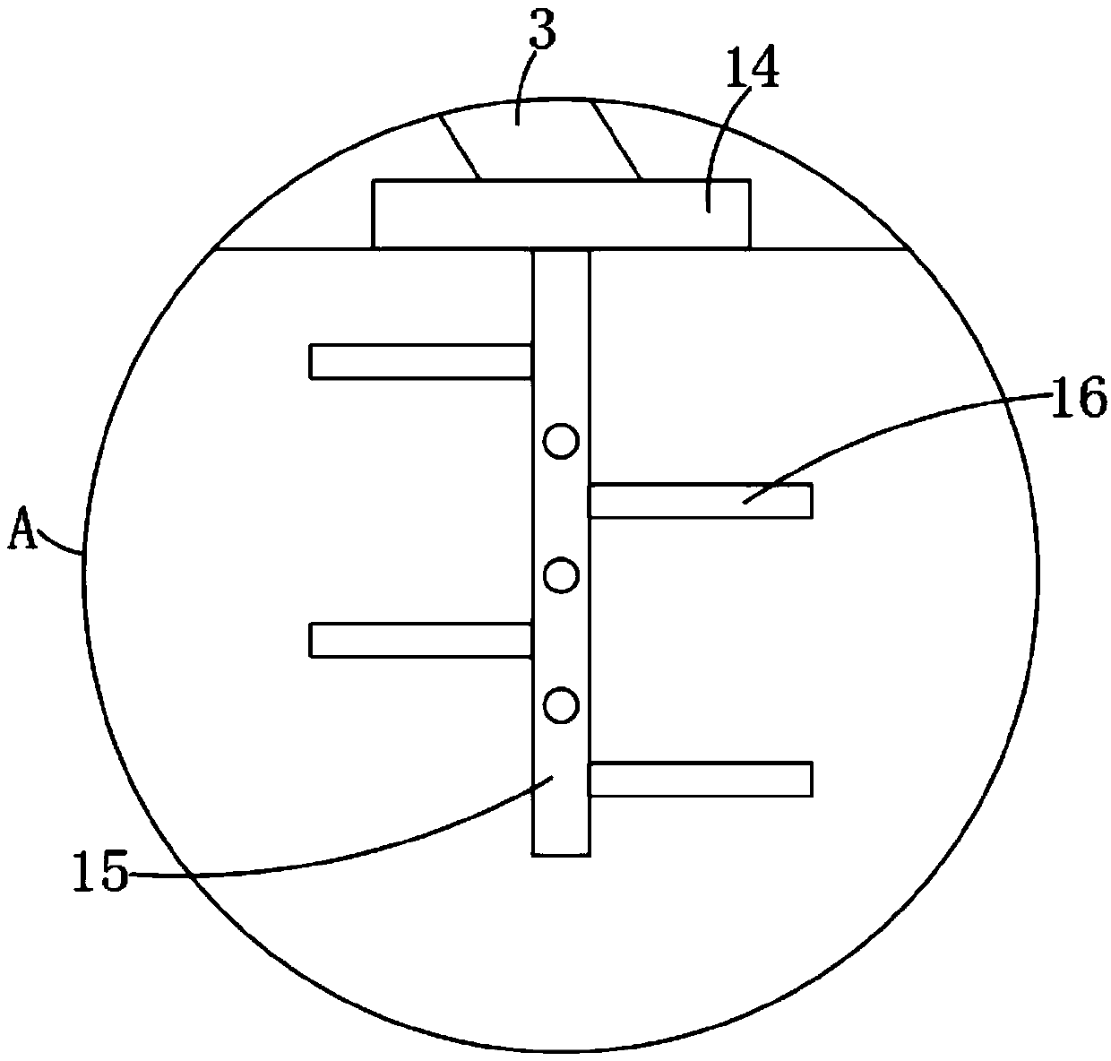
[0021] refer to Figure 1-3 , a support structure for LED street lights, including a first street light pole 1 and a second street light pole 2, the upper end of the first street light pole 1 is fixedly connected with the bottom side wall of the second street light pole 2, the first street light pole 1 and the second street light pole The poles 2 are all round hollow poles, saving materials and allowing wires to pass through; the diameter of the second light pole 2 is smaller than the diameter of the first light pole 1, which reduces the resistance of the second light pole 2 to the wind at a high place, and can also reduce the second light pole 2. The bearing capacit...
PUM
 Abstract
Description
Claims
Application Information
PatSnap Eureka turns technology decisions into work you can execute. Powered by our Innovation Knowledge Graph, it runs expert workflows across engineering, life sciences, materials and intellectual property. Get your review-ready output in minutes.


