
Concrete performance test experimental device

A technology for testing experiments and concrete, which is applied in the field of concrete performance testing experimental devices, which can solve the problems of generating a large amount of dust and not being able to handle dust, and achieve the effects of cost saving, pollution reduction and simple operation

Pending Publication Date: 2020-06-30
LANZHOU UNIVERSITY OF TECHNOLOGY
View PDF0 Cites 3 Cited by
  • Summary
  • Abstract
  • Description
  • Claims
  • Application Information

AI Technical Summary

Problems solved by technology

[0004] The purpose of the present invention is to solve the shortcomings in the prior art that a large amount of dust will be generated when the concrete is broken, and the existing testing device cannot handle the dust, and proposes a concrete performance testing experimental device

Method used


Image

  • Concrete performance test experimental device
  • Concrete performance test experimental device
  • Concrete performance test experimental device

Examples


Embodiment 1

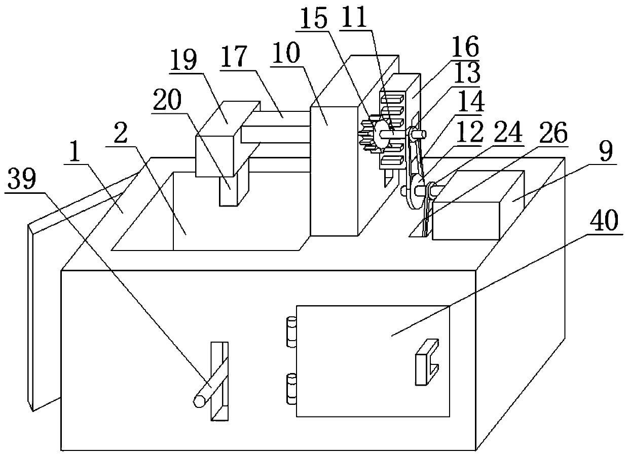
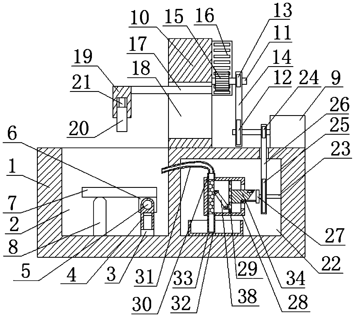
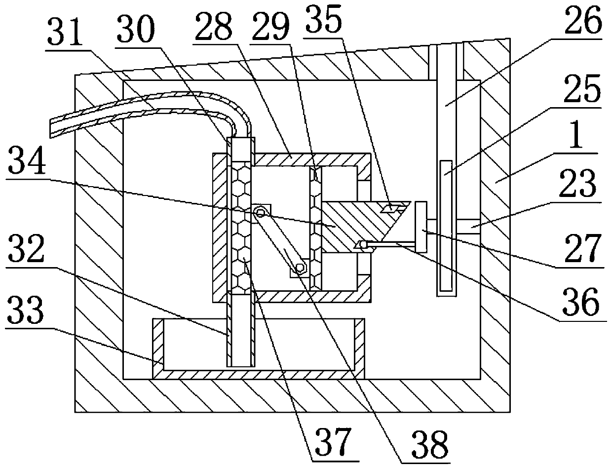
[0028] refer to Figure 1-5 , a concrete performance testing experimental device, comprising a pressure sensor 21 and a base 1, the top of the base 1 is provided with a first groove 2, the bottom of the first groove 2 is fixedly installed with a fixing seat 3, and the fixing seat 3 is slidably installed with a The sliding sleeve 4, that is, the fixed seat 3 and the sliding sleeve 4 are relatively slidably connected. The sliding sleeve 4 is provided with a round hole, and a round rod 5 is installed for rotation in the round hole. One end of the round rod 5 is fixedly installed with a fixed block 6, and the fixed block 6 The top of the first groove 2 is fixedly installed with a backing plate 7, and the bottom of the first groove 2 is fixedly installed with a support plate 8. The support plate 8 matches the backing plate 7 and is used to support the backing plate 7. The support plate 8 and the backing plate 7 correspond to each other. Contact but not connected, when the sliding s...

Embodiment 2

[0038] refer to Figure 1-5 , a concrete performance testing experimental device, including a pressure sensor 21 and a base 1, the top of the base 1 is provided with a first groove 2, the bottom of the first groove 2 is fixed with a fixing seat 3 by screws, and slides on the fixing seat 3 A sliding sleeve 4 is installed, that is, the fixed seat 3 is relatively slidingly connected with the sliding sleeve 4, and a round hole is provided on the sliding sleeve 4, and a round rod 5 is installed for rotation in the round hole. One end of the round rod 5 is welded with a fixed block 6, and the fixed block The top of 6 is fixed with a backing plate 7 by screws, and the bottom of the first groove 2 is fixed with a support plate 8 by screws. The support plate 8 cooperates with the backing plate 7 to support the backing plate 7. The support plate 8 In contact with but not connected to the backing plate 7, when the sliding sleeve 4 is lifted, one end of the backing plate 7 is raised, so t...


PUM


Abstract

The invention belongs to the technical field of building material detection devices, and especially relates to a concrete performance test experiment device. A large amount of dusts can be generated when existing concrete is crushed, but an existing testing device cannot treat dust. The device comprises a pressure sensor and a base, a first groove is formed in the top of the base, a fixed seat isfixedly mounted at the bottom of the first groove, a sliding sleeve is slidably mounted on the fixed seat, a round hole is formed in the sliding sleeve, a round rod is rotationally mounted in the round hole, a fixed block is fixedly mounted at one end of the round rod, and a base plate is fixedly mounted at the top of the fixed block. By arranging the base plate, concrete can be placed on the baseplate and the base plate can be lifted up during testing, so that the tested and broken concrete can be quickly poured out; and a motor drives a pressing column to perform testing, and meanwhile, allstructures in a shell can be driven to be linked, so that dust generated by the broken concrete is sucked into water.

Description

technical field [0001] The invention relates to the technical field of building material testing devices, in particular to an experimental device for testing concrete properties. Background technique [0002] The performance of concrete includes many kinds. The viscosity of uncured concrete is its most important property, while the bearing strength of solidified concrete is its most important property. The bearing strength of concrete after solidification determines the quality of concrete built. The strength of the building, in order to ensure the quality of the concrete, performance testing is required before the concrete is put into use. [0003] In the prior art, when the performance of concrete is usually tested, the concrete is crushed mainly through high pressure, and the performance of the concrete is judged by observing the force required to crush the concrete. A large amount of dust is produced, and the existing test device cannot handle the dust, so a new device ...

Claims


Application Information

Patent Timeline
Patent Type & Authority Applications(China)
IPC IPC(8): G01N3/02G01N3/30
CPCG01N3/02G01N3/30
Inventor 乔宏霞朱飞飞魏智强曹辉薛翠真冯琼李琼张云升路承功付勇杨安汪丽娟
Owner LANZHOU UNIVERSITY OF TECHNOLOGY
Learn More