
Dual-control dynamic compensation transformer

A technology of dynamic compensation and dual control, applied in the field of transformers, can solve the problems of incapable of capacitive switching programming, poor triggering, etc., and achieve the effect of being conducive to simultaneous triggering, increasing equipment cost, and good trigger synchronization

Pending Publication Date: 2020-06-30
NANTONG HAIWANG ELECTRIC
View PDF6 Cites 0 Cited by
  • Summary
  • Abstract
  • Description
  • Claims
  • Application Information

AI Technical Summary

Problems solved by technology

[0003] In order to overcome the problems existing in the prior art that the capacitor switching cannot be programmed according to the actual needs and the specific trigger is not good, the present invention provides a dual-control dynamic compensation transformer

Method used


Image

  • Dual-control dynamic compensation transformer
  • Dual-control dynamic compensation transformer

Examples


Embodiment Construction

[0023] The present invention will be described in further detail below in conjunction with the accompanying drawings and embodiments. It should be understood that the specific embodiments described here are only used to explain the present invention, not to limit the present invention.

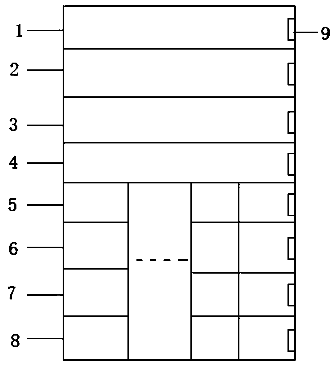
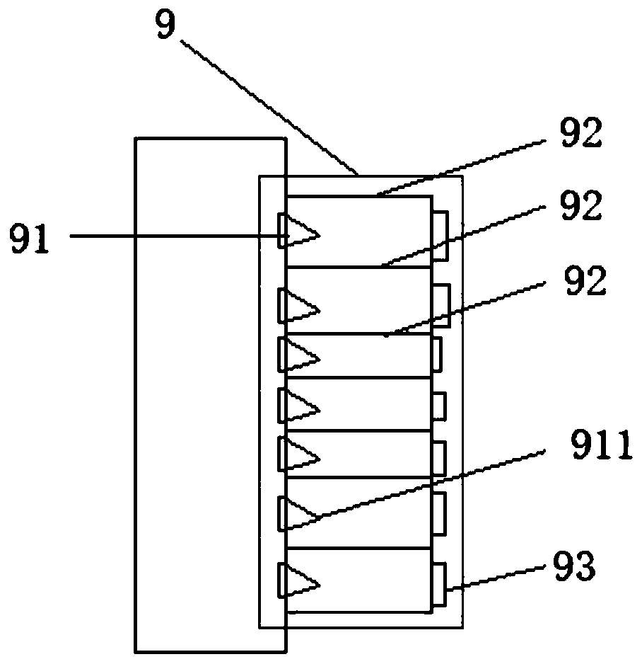
[0024] Please see figure 1 , is a structural schematic diagram of a preferred embodiment of a dual-control dynamic compensation transformer of the present invention, a dual-control dynamic compensation transformer, including a transformer housing, and a transformer main body 1, which is characterized in that it also includes intelligent reactive power compensation acquisition control Unit 2, PLC controller 3, general protection switch 4, several dynamic compensation circuits and ion radiator 9 uniformly arranged on the inner wall of the transformer shell.

[0025] In this embodiment, the dynamic compensation circuit includes a fuse 5, a reactor group 6, a compensation capacitor 7 and a filter...


PUM


Abstract

The invention provides a dual-control dynamic compensation transformer, which comprises a transformer shell and a transformer main body (1), and is characterized by further comprising an intelligent reactive compensation acquisition control unit (2), a PLC (Programmable Logic Controller) (3), a main protection switch (4), a plurality of dynamic compensation loops and ion radiators (9) uniformly arranged on the inner wall of the transformer shell. And the dynamic compensation loop comprises a fuse (5), a reactor group (6), a compensation capacitor (7) and a filter (8) which are connected in sequence. According to the application, the phase-controlled reactor and the PLC are added into the dynamic reactive power compensation circuit, so that the special requirements of different customers onreactive power compensation control can be better met, and the protection function and the switching function of the reactive power compensation controller are more fully applied.

Description

technical field [0001] The invention relates to the technical field of transformers, in particular to a double-controlled dynamic compensation transformer. Background technique [0002] With the rapid growth of my country's economy, it is imperative to build a smart grid. The intelligent transformer adapts to the development direction of intelligent, energy-saving, efficient and reliable power supply in the field of power transformation. It can track the load change through the intelligent controller to automatically supplement the reactive component, and upload it to the power supply background synchronously to ensure high-quality, efficient and reliable power supply, greatly reducing the power consumption of the transformer. The no-load loss is about 70% to 80%. Due to the frequent start-up and the emergence of a large number of impact load equipment, the quality of the power grid is very poor. In order to ensure the normal and reliable operation of electrical equipment, ...

Claims


Application Information

Patent Timeline
Patent Type & Authority Applications(China)
IPC IPC(8): H02J3/18H01F27/02H01F27/08H01F27/22
CPCH02J3/1864H01F27/025H01F27/08H01F27/22Y02E40/30
Inventor 戴月平
Owner NANTONG HAIWANG ELECTRIC
Learn More