Briquetting machine

A dough making machine and transmission device technology, applied in the field of dough making machines, can solve the problems of unsatisfactory small bread dough making, inconvenient maintenance, complicated structure, etc., and achieve the effect of low noise, good safety in use and stable operation

Pending Publication Date: 2020-07-03
ZHEJIANG TIANXI KITCHEN APPLIANCE CO LTD
View PDF8 Cites 0 Cited by
  • Summary
  • Abstract
  • Description
  • Claims
  • Application Information

AI Technical Summary

Problems solved by technology

The above-mentioned noodle production equipment has a complex structure, high cost, and inconvenient maintenance, and can only be used for noodle production and kneading large dough, and cannot satisfy the production of small dough such as small breads and snacks.

Method used


Image

  • Briquetting machine
  • Briquetting machine
  • Briquetting machine

Examples


Embodiment 1

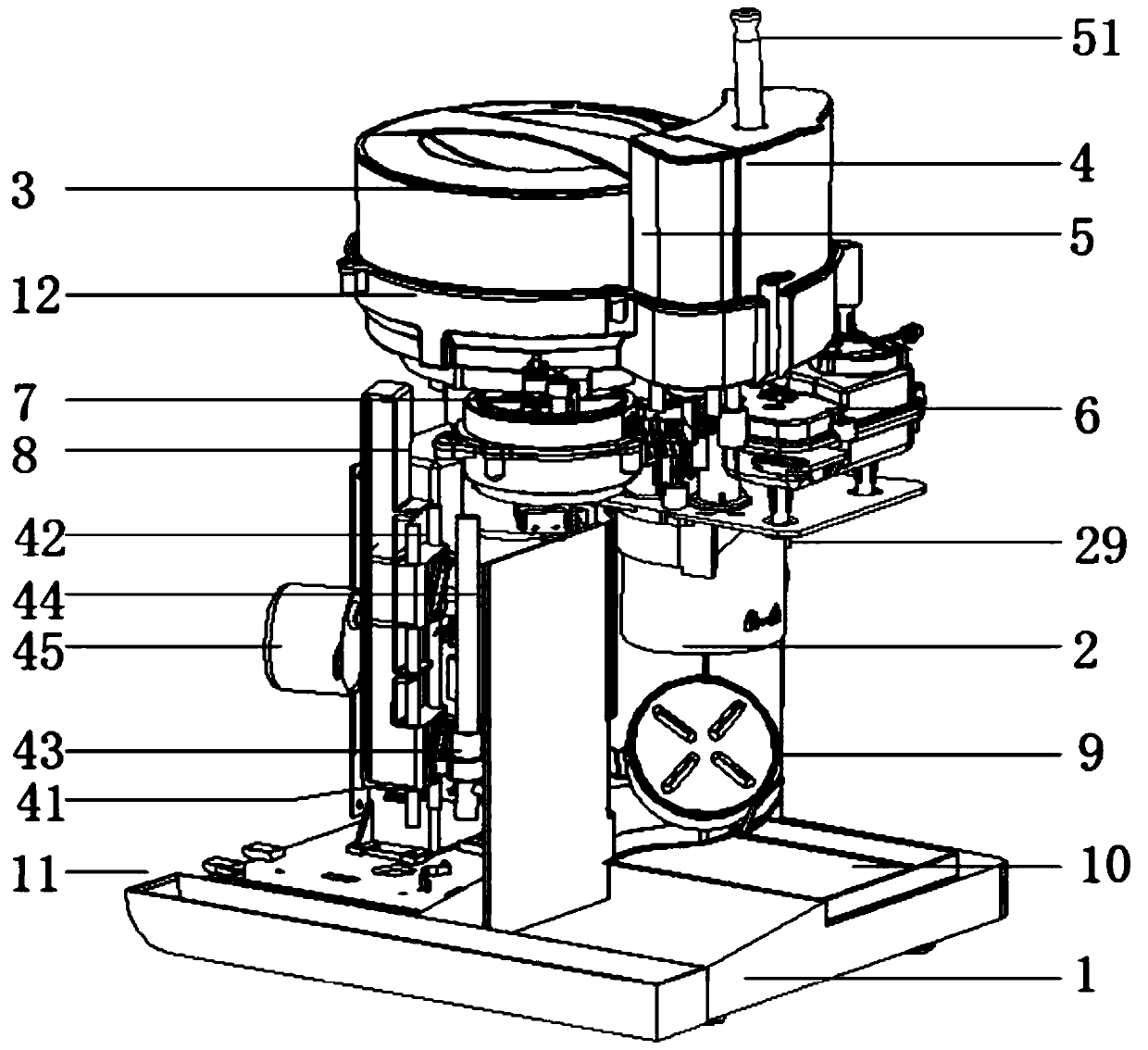
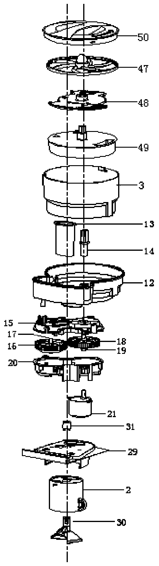
[0031] Embodiment one, such as Figure 1-8As shown, a dough making machine according to an embodiment of the present invention includes a base 1, a mixing container 2, a powder storage container 3, a water storage container 4, an oil storage container 5, a first transmission device 6, a second transmission device 7, The third transmission device 8 and the tray 9, the powder receiving box 10 is fixed on one side of the top surface of the base 1, and the powder receiving box 10 is located below the mixing container 2, and the other side of the top surface of the base 1 is fixed There is a dough box 11, the powder storage container 3 is fixed on the upper side of the base 1, and the water storage container 4 and the oil storage container 5 are connected to one side of the powder storage container 3, the The bottom ends of the powder storage container 3, the water storage container 4 and the oil storage container 5 are fixed with a second container seat 12, and the bottom ends of ...

Embodiment 2

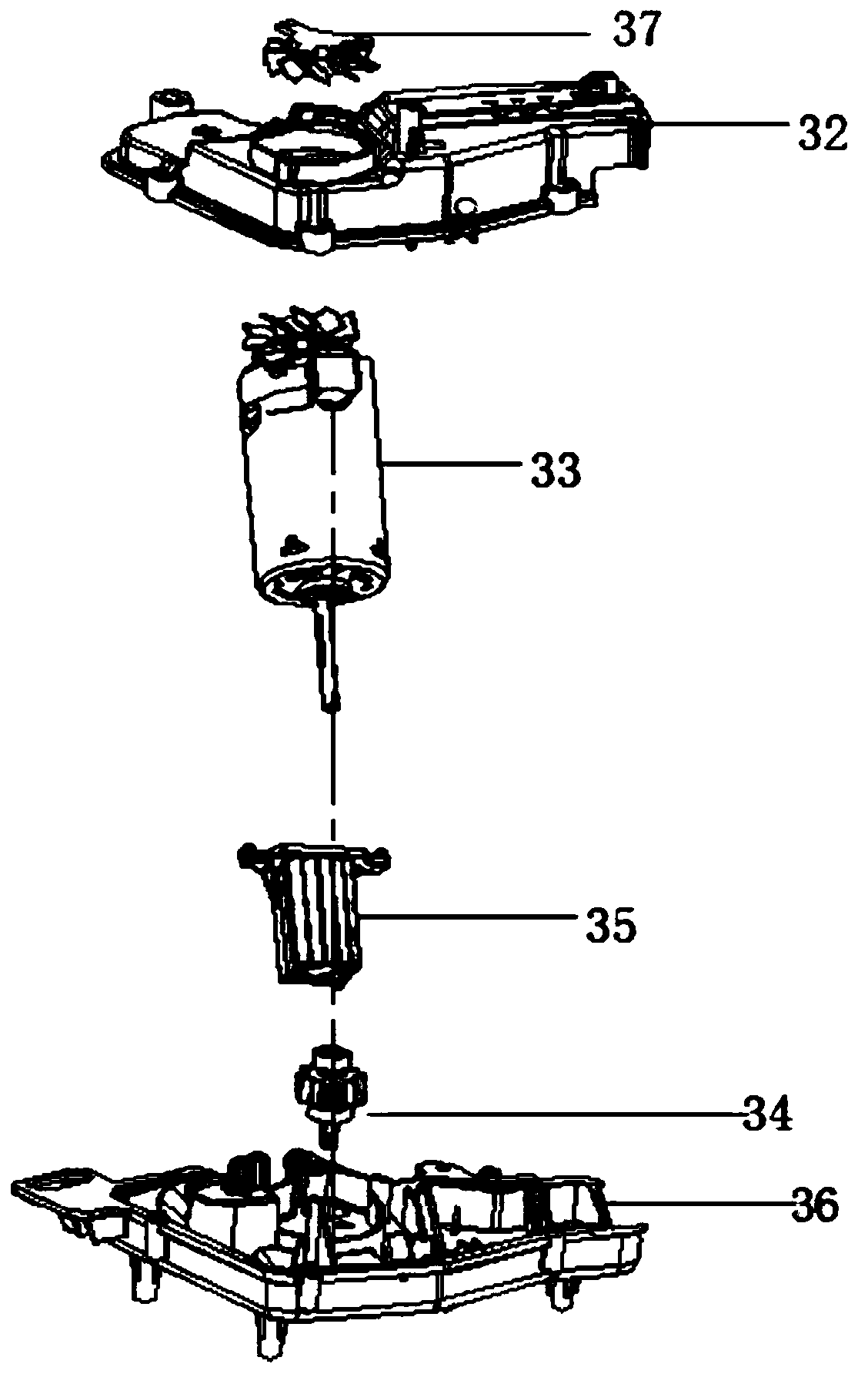
[0032] Embodiment two, such as figure 2 As shown, the first transmission 6 includes a first transmission cover 32, a first transmission motor 33, an output gear 34, a power output shaft 35 and a first transmission box 36; the first transmission cover 32 is installed The first transmission box 36 is closely connected with the first transmission box 36, and the first transmission motor 33, the power output shaft 35, and the output gear 34 are installed in the first transmission box 36 respectively. Inside, the first transmission motor 33 is connected to the power output shaft 35, the power output shaft 35 is connected to the output gear 34, and the bottom movable shaft of the output gear 34 runs through the first transmission device The box 36 is connected to the stirring drive head 31 .

Embodiment 3

[0033] Embodiment three, such as figure 2 As shown, the top of the first transmission cover 32 is fixed with a cooling fan 37 at the position corresponding to the first transmission motor 33; the cooling fan 37 can accelerate the heat dissipation of the device, which is more conducive to the safety and use of the device.


PUM


Abstract

The invention discloses a briquetting machine. The machine comprises a base, a mixing container, a powder storage container, a water storage container, an oil storage container, a first transmission device, a second transmission device, a third transmission device and a tray. A powder receiving box is fixed on one side of the top surface of the base, a dough receiving box is fixed on the other side of the top surface of the base, the powder storage container is fixed on the upper side of the base, one side of the powder storage container is connected with the water storage container and the oil storage container, a second container seat is fixed on the bottom end of the powder storage container, water storage container and oil storage container, the first transmission device and the secondtransmission device are fixed on the bottom end of the second container seat, a lower hopper is fixed on one side of the bottom end of the powder storage container, the bottom end of the lower hopperis connected to one side of the top end of the mixing container, a powder tray transmission rod is arranged in the middle of the bottom part of the powder storage container, and the bottom end of thepowder tray transmission rod penetrates the second container seat and is connected to the second transmission device.

Description

technical field [0001] The invention relates to the technical field of food processing devices, in particular to a dough making machine. Background technique [0002] In people's daily life, pasta food, scones, pancakes, bread, and snacks have become an indispensable part of life. With the busy work, simple and fast food is favored by people of different levels. The Chinese patent with publication number CN101147500A discloses a continuous vacuum noodle kneading machine and noodle production equipment provided with the noodle kneading machine, wherein the continuous vacuum noodle kneading machine includes a frame, a noodle kneading container, a noodle feeding device, a water supply device, a control The circuit and the dough container are equipped with a discharge device, which also includes a vacuum device and a stirring and conveying device. The stirring and conveying device cooperates with the discharge device to fill the pushed dough into the discharge device and seal th...

Claims


Application Information

Patent Timeline
Patent Type & Authority Applications(China)
IPC IPC(8): A21C1/02A21C1/14
CPCA21C1/02A21C1/1425A21C1/1465
Inventor 不公告发明人
Owner ZHEJIANG TIANXI KITCHEN APPLIANCE CO LTD
Why Eureka
Try Eureka