Lifting and cavity combined exhibition equipment for museums
What is AI technical title?
AI technical title is built by Patsnap AI team. It summarizes the technical point description of the patent document.
A museum, combined technology, applied in the field of combined exhibition equipment
Active Publication Date: 2020-12-22
浙江黎盛新材料科技有限公司
View PDF2 Cites 0 Cited by
Summary
Abstract
Description
Claims
Application Information
AI Technical Summary
This helps you quickly interpret patents by identifying the three key elements:
Problems solved by technology
Method used
Benefits of technology
Problems solved by technology
[0005] However, the above-mentioned museum exhibition equipment and most existing museum exhibition equipment with lifting and inner cavity combination cannot give viewers a new visual experience when exhibiting items.
Method used
Image
Click on the blue label to locate the original text in one second.
Reading with bidirectional positioning of images and text.
Examples
Embodiment 1
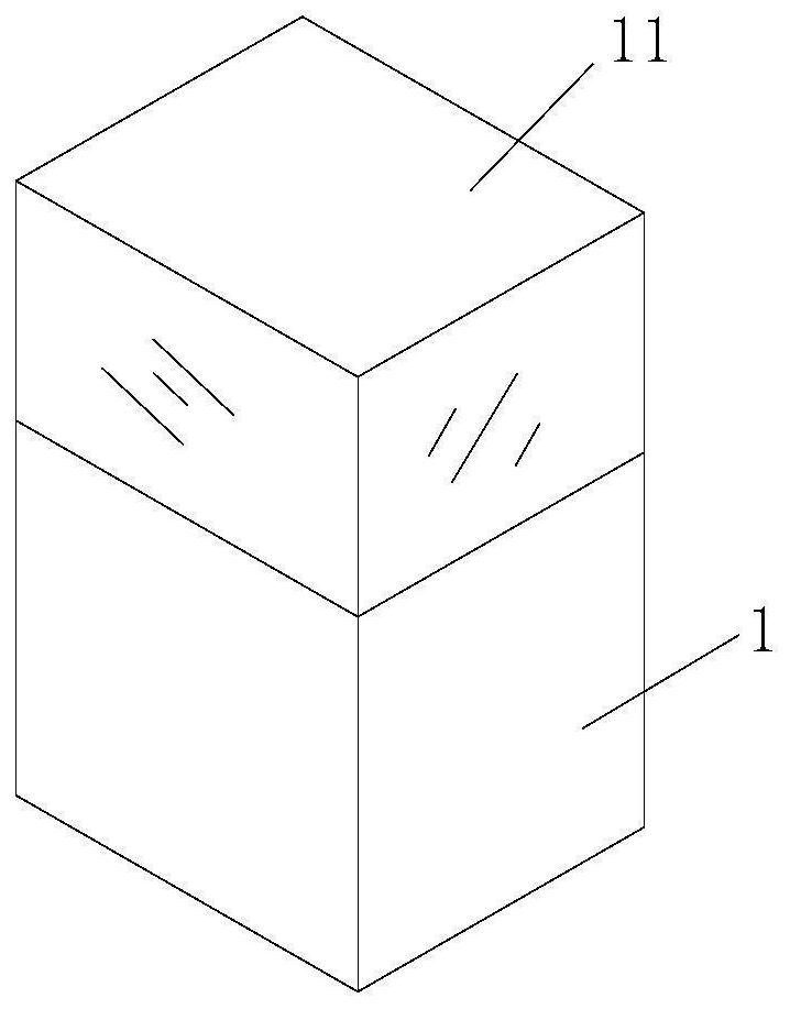
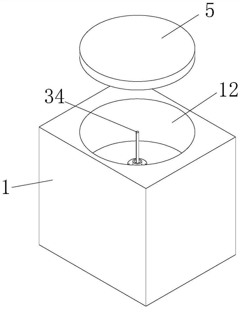
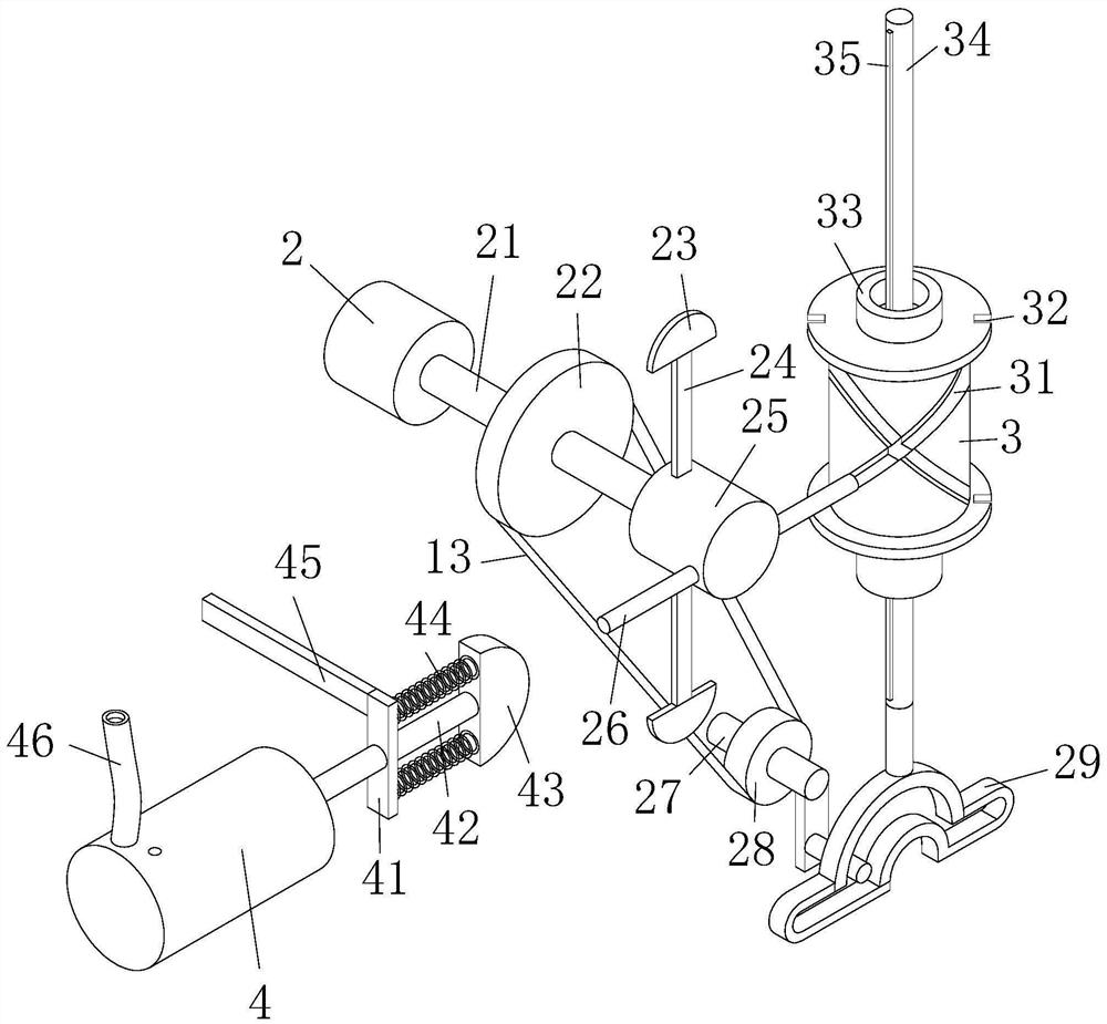
[0041] Example 1: Please refer to figure 1 , figure 2 ,and image 3 , the museum uses a combination of lifting and inner chamber exhibition equipment, including an exhibition stand 1, a transparent cover 11 is arranged above the exhibition stand 1, an inner chamber 12 is opened on the upper surface of the exhibition stand 1, and an inner upper end of the inner chamber 12 is provided with A circular carrying platform 5, the inner cavity 12 is provided with a transmission device, the transmission includes a motor 2 and a rotating shaft 21, the right side of the motor 2 is fixedly connected with the left side of the rotating shaft 21, the side surface of the motor 2 and the inner cavity 12 The inner walls are fixedly connected together, the side surface of the rotating shaft 21 is fixedly sleeved with a runner 22, the right side of the runner 22 is fixedly connected with a cylinder 25, and the left end of the upper and lower sides of the cylinder 25 is fixedly connected with a ...
Embodiment 2
[0046] Example 2: Please refer to Figure 4 , on the basis of Embodiment 1, a triangular platform-51 is fixedly connected to the upper surface of the circular carrying platform 5, and the inclined surface of the triangular platform-51 is attached with magnetism, and two rectangular magnetic blocks are arranged on the inclined surface of the triangular platform-51 One 52, two rectangular magnetic blocks one 52 and the slope of the triangular platform one 51 are connected together by magnetic force.
[0047] When in use, by being provided with a triangular platform-51 and a rectangular magnetic piece-52 on the circular carrying platform 5, when works such as exhibition calligraphy and painting, the works such as calligraphy and painting are unfolded and placed on the triangle by two rectangular magnetic pieces-52. On stage one 51, combined with the rotating function of the rotating device, people from different directions can see the exhibits.
Embodiment 3
[0048] Example 3: Please refer to image 3 and Figure 5 , on the basis of embodiment one, the front end of cylinder one 25 is provided with a blower, and blower comprises semicircle block two 43, round rod three 42 and cylinder three 4, and the front of round rod three 42 and cylinder three 4 The internal pistons are fixedly connected together, the back of the round rod three 42 is fixedly connected with the front middle part of the semicircular block two 43, the middle part of the round rod three 42 is movably socketed with a rectangular vertical block 41, and the left upper end of the rectangular vertical block 41 A rectangular cross bar 45 is fixedly connected, and the left end of the rectangular cross bar 45 is fixedly connected with the inner wall of the inner chamber 12. Two springs 44 are arranged between the rectangular vertical block 41 and the semicircular block 2 43, and the two springs 44 are respectively located The upper and lower ends of the round rod three 42...
PUM
Abstract
The invention relates to the technical field of combined exhibition equipment. The invention further discloses lifting and inner cavity combined type exhibition equipment for the museum. The equipmentcomprises an exhibition stand, a transparent cover is arranged above the exhibition stand; an inner cavity is formed in the upper surface of the exhibition stand; a circular bearing table is arrangedat the upper end in the inner cavity; a transmission device is arranged in the inner cavity; the transmission device comprises a motor and a rotating shaft; according to the invention, the semicircular blocks I are driven to rotate through the rotation of the cylinder I; the two semicircular blocks I rotate to extrude the semicircular block II in a reciprocating manner; therefore, gas in the cylinder III is pressed into the cylindrical transparent cover in a reciprocating manner through the hose and the gas outlet hole; when exhibitions such as feathers or leaves of precious birds are exhibited, the exhibitions such as the feathers and the leaves are blown up through gas, so that a viewer can see the condition that the feathers, the leaves and the like are blown up and then fall down, andbrand-new visual enjoyment is provided for the viewer.
Description
technical field [0001] The invention relates to the technical field of combined exhibition equipment, in particular to the combined exhibition equipment for lifting and inner chambers used in museums. Background technique [0002] Museums are places that collect, collect, display and study objects representing natural and human cultural heritage, and classify those objects of scientific, historical or artistic value, including cultural and educational institutions that provide knowledge, education and appreciation for the public , building, location or social institution. [0003] For example, a Chinese patent discloses a display cabinet for museum collections, CN108926191A. By adopting a cabinet body, a glass cover and a support plate, the glass cover is a glass cover made of dimming glass, and the glass cover is arranged on the top of the cabinet body. The support plate is fixedly arranged at the lower end of the cabinet body; a cover plate is provided on the upper end su...
Claims
Application Information
Patent Timeline
Application Date:The date an application was filed.
Publication Date:The date a patent or application was officially published.
First Publication Date:The earliest publication date of a patent with the same application number.
Issue Date:Publication date of the patent grant document.
PCT Entry Date:The Entry date of PCT National Phase.
Estimated Expiry Date:The statutory expiry date of a patent right according to the Patent Law, and it is the longest term of protection that the patent right can achieve without the termination of the patent right due to other reasons(Term extension factor has been taken into account ).
Invalid Date:Actual expiry date is based on effective date or publication date of legal transaction data of invalid patent.

