
Surface layer composite manufacturing equipment for vacuum insulation board

A vacuum heat insulation board and surface layer technology, which is applied to heat exchange equipment, mechanical equipment, and pipelines through heat insulation, can solve the problem of poor heat insulation of vacuum heat insulation boards, affecting the fluidity and adhesion of sprayed films, and preventing air spraying. The film cannot completely cover the inorganic fiber core material, etc., to reduce environmental pollution and increase the pressing force

Inactive Publication Date: 2020-07-03
邓家珍
View PDF6 Cites 2 Cited by
  • Summary
  • Abstract
  • Description
  • Claims
  • Application Information

AI Technical Summary

Problems solved by technology

[0003] In the prior art, a pressing machine is often used for the production of vacuum insulation panels. After pressing, the air-blocking spray film is attached to the surface. However, the disadvantage of this method is that the air-blocking spray film cannot completely cover the surface of the inorganic fiber core material. , and because the surface of the material that has just been pressed has a certain temperature, it will affect the fluidity and adhesion of the sprayed film on its surface, resulting in poor thermal insulation of the vacuum insulation panel after production. Therefore, a vacuum insulation panel surface Composite production equipment came into being

Method used


Image

  • Surface layer composite manufacturing equipment for vacuum insulation board
  • Surface layer composite manufacturing equipment for vacuum insulation board
  • Surface layer composite manufacturing equipment for vacuum insulation board

Examples


Embodiment Construction

[0024] The following will clearly and completely describe the technical solutions in the embodiments of the present invention with reference to the accompanying drawings in the embodiments of the present invention. Obviously, the described embodiments are only some, not all, embodiments of the present invention. Based on the embodiments of the present invention, all other embodiments obtained by persons of ordinary skill in the art without making creative efforts belong to the protection scope of the present invention.

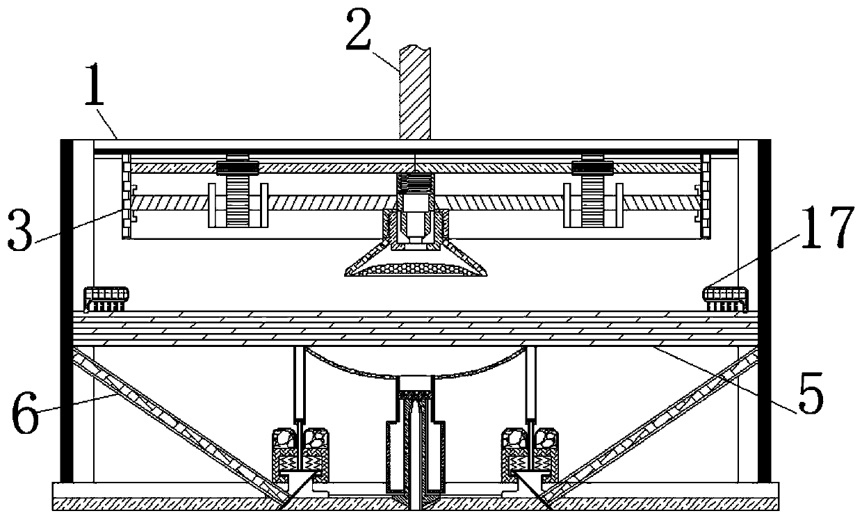
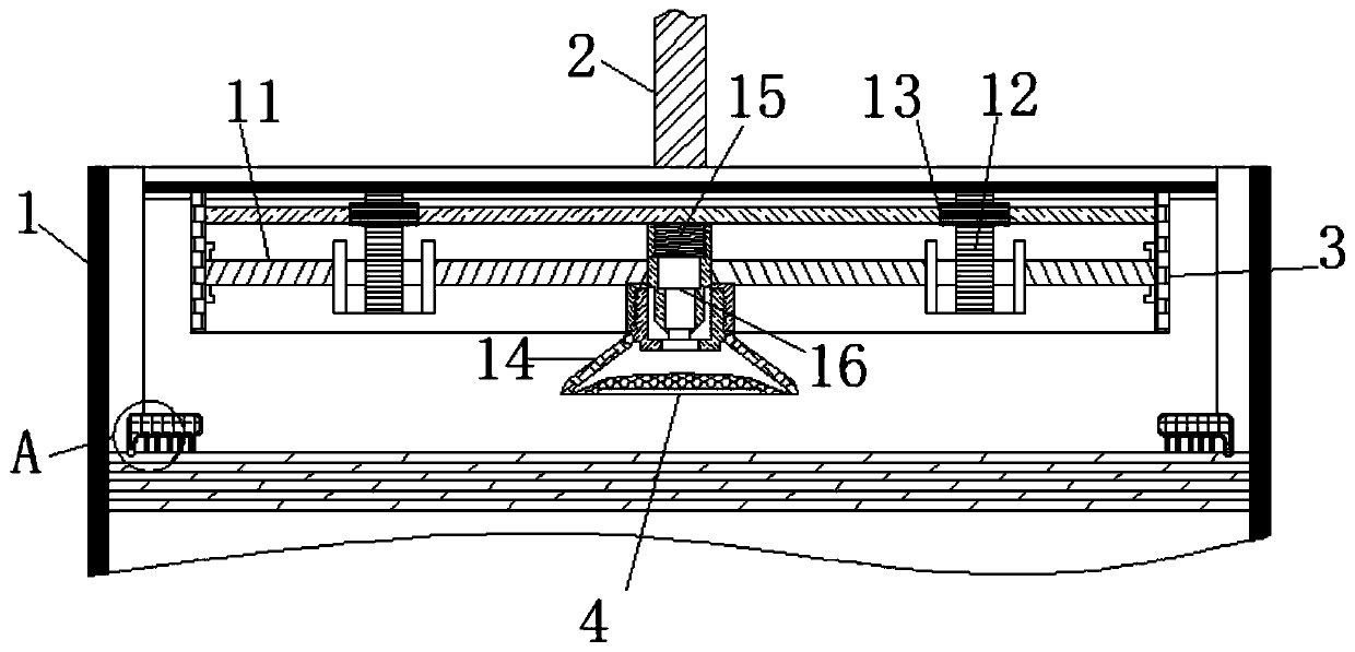
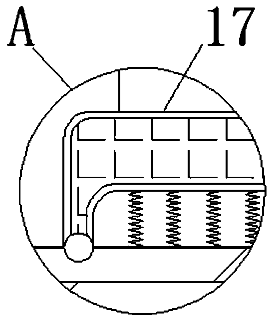
[0025] see Figure 1-6 , a vacuum heat insulation board surface compound production equipment, comprising a shell 1, the top of the shell 1 is fixedly connected with a push rod 2, the lower end of the push rod 2 is fixedly connected with a pressing box 3, and the inside of the pressing box 3 is movably connected with a screw rod 11. The screw rod 11 plays the role of driving the rotating shaft 15 to rotate, and undertakes the movement of the tooth plate 12. Th...


PUM


Abstract

The invention relates to the technical field of manufacturing of thermal insulation boards of building insulation materials, and discloses surface layer composite manufacturing equipment for a vacuuminsulated board. The equipment comprises a shell, wherein the top of the shell is fixedly connected with a push rod, the lower end of the push rod is fixedly connected with a pressing box, the interior of the pressing box is movably connected with a film covering piece, a composite table is movably connected to the position, below the film covering piece, in the shell, the bottom of the compositetable is movably connected with an extrusion rod, the lower end of the extrusion rod is movably connected with a lifting rod, the upper end of the lifting rod is in sliding connection with an ejectionplate, and the surface of the ejection plate is movably connected with a roller. Since the position of the film covering piece is higher than the position where the pressing box is located, the filmcovering piece makes contact with a material first, so that the material can feed the acting force back to the film covering piece, and at the same time, the non-stressed end of the lifting rod is lifted to push the ejection plate out, so that the material is pressed and formed by the clamping force on the upper surface and the lower surface, and the effect of uniformly distributing a spraying film is achieved through simultaneous film spraying and pressing.

Description

technical field [0001] The invention relates to the technical field of manufacturing heat insulation boards of building heat insulation materials, in particular to a composite manufacturing equipment for the surface layer of vacuum heat insulation boards. Background technique [0002] There are many kinds of thermal insulation materials used in buildings, and the most common thermal insulation materials used are two types, inorganic thermal insulation materials and organic thermal insulation materials. Among them, inorganic material vacuum insulation panels are used more, and vacuum insulation panels are made of inorganic materials. It is made of fiber core material and high gas barrier composite film, which has the characteristics of high-efficiency insulation board. [0003] In the prior art, a pressing machine is often used for the production of vacuum insulation panels. After pressing, the air-blocking spray film is attached to the surface. However, the disadvantage of t...

Claims


Application Information

Patent Timeline
IPC IPC(8): B08B5/04B29C41/20B29C41/42B29C41/34F16L59/065
CPCB08B5/04B29C41/20B29C41/34B29C41/42F16L59/065
Inventor 邓家珍田展旭徐浩然
Owner 邓家珍
Learn More