
A coal mine goaf filling and grouting equipment

A goaf and grouting technology, applied in mining equipment, filling, earthwork drilling, etc., can solve problems such as roof caving, economic loss, surface subsidence, etc., and achieve the effect of preventing solidification and ensuring solidification.

Active Publication Date: 2021-09-03
山东省地矿工程集团有限公司
View PDF0 Cites 0 Cited by
  • Summary
  • Abstract
  • Description
  • Claims
  • Application Information

AI Technical Summary

Problems solved by technology

[0002] The hazards of underground mined-out areas to mining projects are significant and cumulatively superimposed, mainly reflected in two aspects: one is the deformation and destruction of ore pillars in the mined-out area, large-scale caving of the roof, and rock movement, resulting in surface subsidence, cracking and subsidence , damage the ground environment and affect open-pit operations, and what is more serious is the casualties and equipment damage caused by the high-speed air waves and shock waves of the sudden collapse of the goaf; on the other hand, during the mining process, the surrounding rock of the goaf is shaken The impact leads to the development of cracks in the rock mass, and even penetrates the surface or connects to the accumulated water in old kilns, causing water inrush accidents, submerging tunnels and working faces, and causing huge economic losses;
[0003] Usually, the coal mine goaf that will be left after the coal mining operation is completed, if the coal mine goaf is not reinforced or backfilled, it will cause subsidence after a long time, causing ground subsidence, forming a subsidence pit on the surface, and forming water accumulation , causing farmland to be unable to cultivate; therefore, a coal mine goaf filling and grouting equipment is needed, which can fill the goaf with grouting, effectively prevent the collapse of the goaf, and ensure the utilization rate of farmland. The accumulated water in the goaf can be pumped out, effectively ensuring the efficient filling of the goaf, and it can also compact the pit dug at the upper end of the goaf to ensure the smoothness of the road surface

Method used


Image

  • A coal mine goaf filling and grouting equipment
  • A coal mine goaf filling and grouting equipment
  • A coal mine goaf filling and grouting equipment

Examples


Embodiment Construction

[0026] The technical solution of the present invention will be further specifically described through the embodiments and in conjunction with the accompanying drawings. In the following description, numerous specific details are set forth in order to provide a thorough understanding of the present invention. However, the present invention can be implemented in many other ways different from those described here, and those skilled in the art can make similar improvements without departing from the connotation of the present invention, so the present invention is not limited by the specific implementations disclosed below.

[0027] In the description of the present invention, it should be noted that the orientation or positional relationship indicated by the terms "upper", "lower", "front", "back", "left", "right" etc. are based on the Orientation or positional relationship, or the orientation or positional relationship that the inventive product is usually placed in use, is onl...


PUM


Abstract

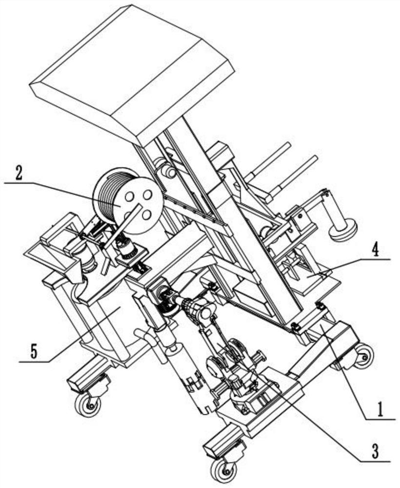
A coal mine goaf filling and grouting equipment includes: a support drilling mechanism, a pumping detection mechanism, an excavating mechanism, a soil pressing mechanism, and a pressurized grouting mechanism. The support drilling mechanism includes: an underframe, a universal wheel, Controller, sliding frame, rack slot, drive motor, push handle frame; the universal wheel is fixedly installed on the lower end surface of the chassis; the lower end surface of the controller is fixedly connected with the upper end surface of the chassis; the rack slot is fixedly installed on the chassis The upper end surface of the sliding frame; the gear on the sliding frame meshes with the rack in the groove on the side end surface of the rack groove; the driving motor is fixedly installed on the side end surface of the sliding frame, and its motor shaft is fixedly connected with the gear on the sliding frame; the push handle frame It is fixedly installed on the rear end surface of the rack groove, thereby driving the drilling motor to move downward; the pumping detection mechanism is fixedly installed on the upper end surface of the sliding frame; the earth digging mechanism and the pressurized grouting mechanism are fixedly installed on the bottom The upper end surface; the soil pressing mechanism is fixedly installed on the baffle plate on the upper end surface of the chassis.

Description

technical field [0001] The invention relates to the technical field of coal mine goaf filling equipment, in particular to a coal mine goaf filling and grouting equipment. Background technique [0002] The hazards of underground mined-out areas to mining projects are significant and cumulatively superimposed, mainly reflected in two aspects: one is the deformation and destruction of ore pillars in the mined-out area, large-scale caving of the roof, and rock movement, resulting in surface subsidence, cracking and subsidence , damage the ground environment and affect open-pit operations, and what is more serious is the casualties and equipment damage caused by the high-speed air waves and shock waves of the sudden collapse of the goaf; on the other hand, during the mining process, the surrounding rock of the goaf is shaken The impact leads to the development of cracks in the rock mass, and even penetrates the surface or connects to the accumulated water in old kilns, causing wa...

Claims


Application Information

Patent Timeline
Patent Type & Authority Patents(China)
IPC IPC(8): E21F15/06E21F15/00E21F16/00E21F17/00
CPCE21F15/005E21F15/06E21F16/00E21F17/00
Inventor 巩超高志友吕涛张雷雷孟祥谊张晓彤王炳凤杨霞张新辉张娟吕鹏高荣政
Owner 山东省地矿工程集团有限公司
Learn More