Data synchronization method between host end and FPGA accelerator

A data synchronization, host-side technology, applied in the computer field, can solve the problem of high synchronization delay

Active Publication Date: 2020-07-03
INSPUR SUZHOU INTELLIGENT TECH CO LTD
View PDF11 Cites 5 Cited by
  • Summary
  • Abstract
  • Description
  • Claims
  • Application Information

AI Technical Summary

Problems solved by technology

[0005] The purpose of this application is to provide a data synchronization method between the host end and the FPGA accelerator, a double-ended memory synchronizer, an FPGA accelerator and a data synchronization system, to solve the synchronization of the traditional synchronization scheme between the host end and the FPGA accelerator high latency issues

Method used


Image

  • Data synchronization method between host end and FPGA accelerator
  • Data synchronization method between host end and FPGA accelerator
  • Data synchronization method between host end and FPGA accelerator

Examples


Embodiment 1

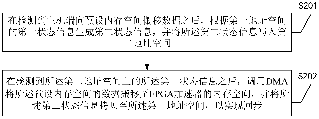
[0037] Embodiment 1 of a data synchronization method between a host end and an FPGA accelerator provided by the present application is introduced below, see figure 2 , embodiment one includes:

[0038] S201. After detecting that the host moves data to the preset memory space, generate second state information according to the first state information in the first address space, and write the second state information into the second address space;

[0039] Wherein, the first address space and the second address space are different address spaces mapped on the host side by the Bar space, the first state information includes the last data frame number and the current data frame number, and the second The two-state information includes the current data frame number and the next data frame number.

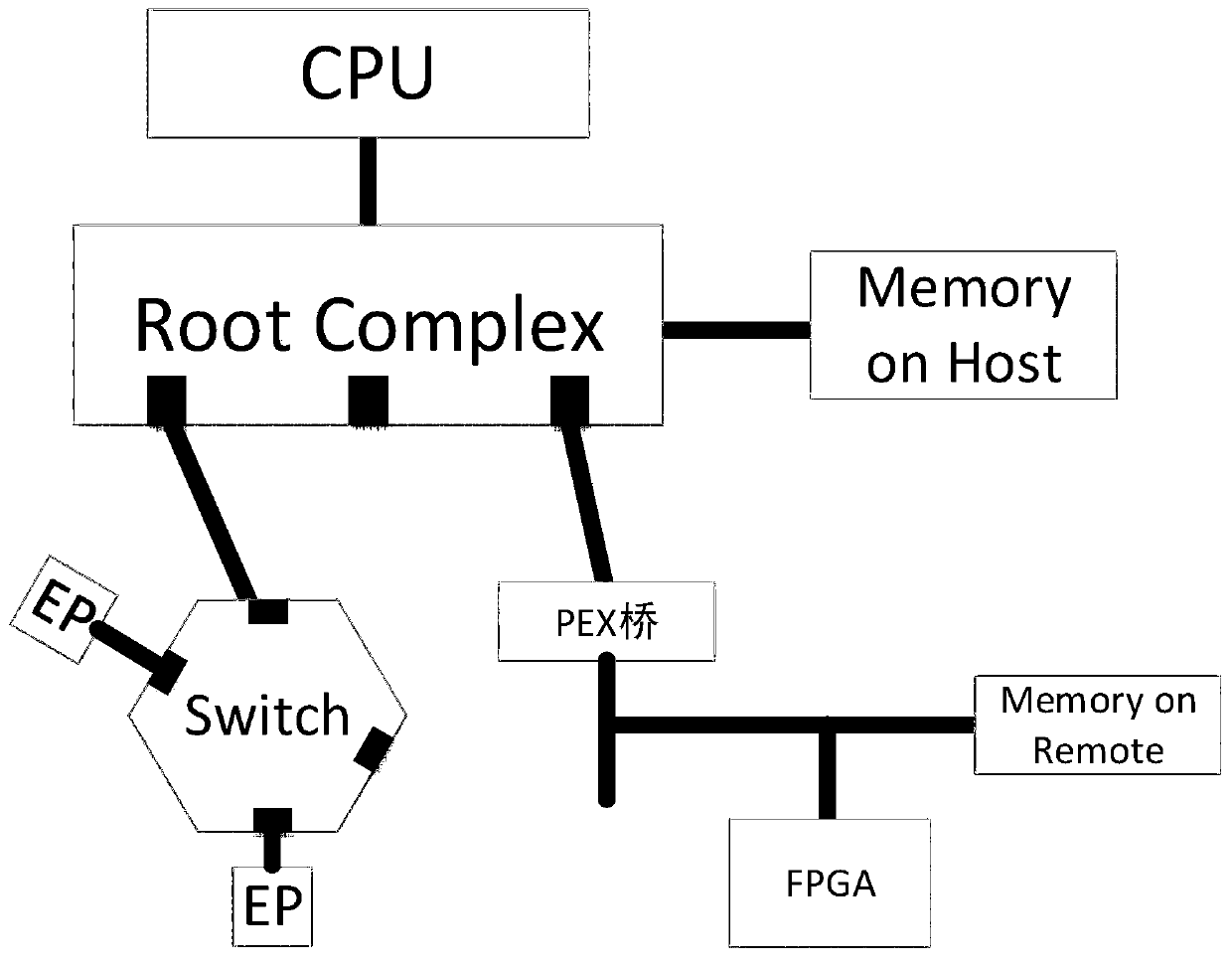
[0040] S202. After detecting the second state information on the second address space, call DMA to move the data in the preset memory space to the memory space of the FPGA accelerator,...

Embodiment 2

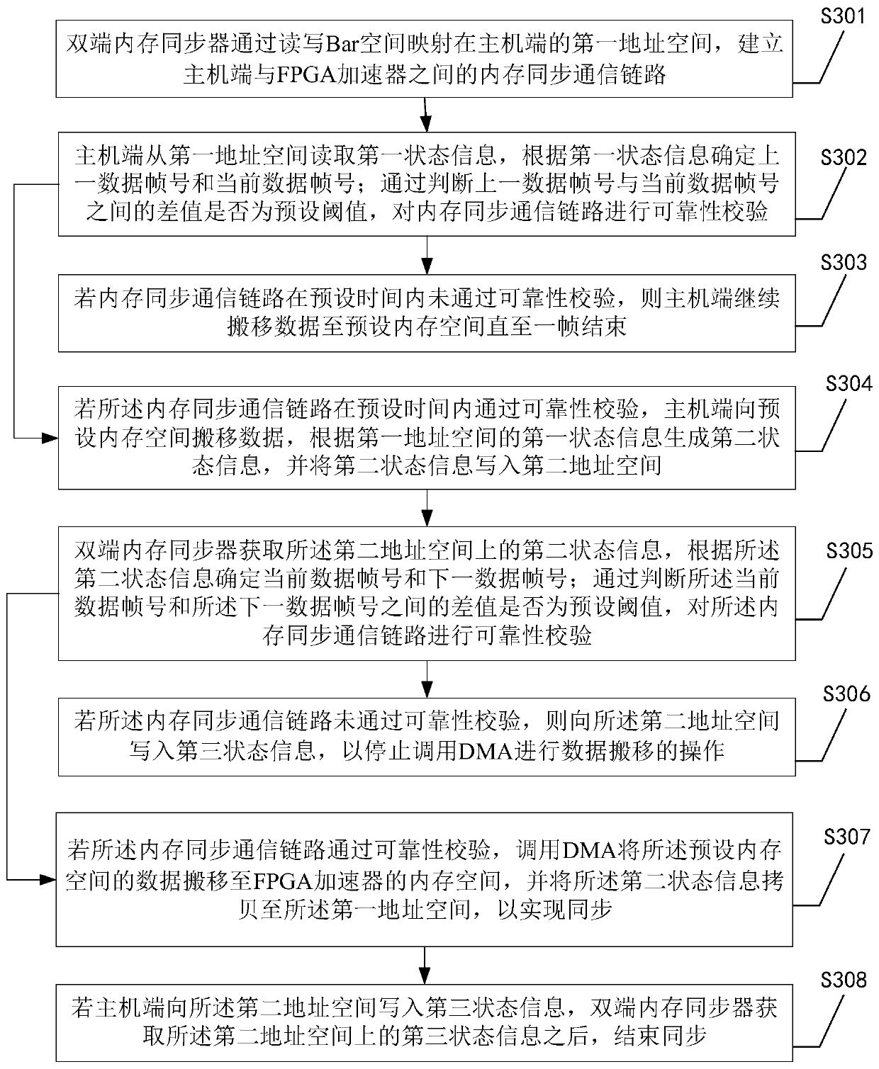
[0048] see image 3 , embodiment two specifically includes:

[0049] S301. The dual-terminal memory synchronizer maps the first address space on the host side by reading and writing the Bar space, and establishes a memory synchronization communication link between the host side and the FPGA accelerator;

[0050] S302. The host terminal reads the first state information from the first address space, and determines the last data frame number and the current data frame number according to the first state information; by judging the difference between the last data frame number and the current data frame number Whether it is a preset threshold, and check the reliability of the memory synchronization communication link;

[0051] S303. If the memory synchronous communication link fails the reliability check within the preset time, the host continues to move data to the preset memory space until the end of one frame;

[0052] S304. If the memory synchronous communication link passe...


PUM


Abstract

The invention discloses a data synchronization method between a host end and an FPGA accelerator, and the method comprises the steps: generating second state information according to the first state information of a first address space after the host end is detected to move data to a preset memory space, and writing the second state information into the second address space; after the second stateinformation on the second address space is detected, DMA is called to move the data in the preset memory space to the memory space of the FPGA accelerator, and the second state information is copiedto the first address space to achieve synchronization. Therefore, according to the method, the data synchronization operation is executed based on the state information on the two address spaces, thecontroller on one side of the FPGA accelerator is used for actively executing double-end memory data synchronization, the data synchronization delay is reduced, and the system throughput rate is increased. In addition, the invention further provides a double-end memory synchronizer, an FPGA accelerator and a data synchronization system, and the technical effects of the double-end memory synchronizer, the FPGA accelerator and the data synchronization system correspond to the technical effects of the method.

Description

technical field [0001] The present application relates to the field of computer technology, in particular to a data synchronization method between a host end and an FPGA accelerator, a dual-end memory synchronizer, an FPGA accelerator and a data synchronization system. Background technique [0002] At present, general-purpose computing systems all use a local bus structure based on PCIe, such as figure 1 As shown, its function is similar to that of the PCI bus, mainly for connecting external devices in the processing system, and the devices mounted on the bus realize point-to-point data communication through the PCIe controller. Compared with the ISA, EISA and MAC buses, the PCIe bus has the advantages of space isolation between the bus and the processor, good scalability, support for dynamic configuration, and end-to-end high bus data bandwidth. [0003] As an emerging accelerator device, FPGA mainly communicates with the processor through the PCIe bus. As a PCIe-Agent dev...

Claims


Application Information

Patent Timeline
Patent Type & Authority Applications(China)
IPC IPC(8): G06F13/16G06F13/28G06F13/42
CPCG06F13/1689G06F13/282G06F13/4221G06F13/4234G06F13/4282G06F15/7889G06F15/17331G06F13/30
Inventor 欧明阳樊嘉恒阚宏伟
Owner INSPUR SUZHOU INTELLIGENT TECH CO LTD
Why Eureka
Try Eureka