Distributed microwave phase control method

A phase control and distributed technology, applied in the direction of microwave heating, etc., can solve the problems of uneven heating, uneven distribution of microwave electric field strength, limited effect, etc., to achieve uniform heating and improve the effect of uneven heating

Inactive Publication Date: 2020-07-03
IND TECH RES INST
View PDF9 Cites 0 Cited by
  • Summary
  • Abstract
  • Description
  • Claims
  • Application Information

AI Technical Summary

Problems solved by technology

[0002] The traditional microwave heating technology uses the magnetron to generate microwaves to heat the object to be heated. However, the distribution of the electric field strength of the microwave in this heating method is prone to unevenness, so that the part of the object to be heated located in the weak electric field area will suffer due to the weaker absorption intensity. A weak electric field produces a low heating area without significant heating, while the part of the heated object located

Method used


Image

  • Distributed microwave phase control method
  • Distributed microwave phase control method
  • Distributed microwave phase control method

Examples


Embodiment Construction

[0040] The implementation of the present invention will be described below with reference to specific examples, and those skilled in the art can easily understand other advantages and effects of the present invention from the content disclosed in this specification.

[0041] It should be noted that the structures, proportions, sizes, etc. shown in the drawings attached to this specification are only used to match the content disclosed in the specification for the understanding and reading of those familiar with this technology, and are not intended to limit the present invention Therefore, it has no technical substantive meaning, and any modification of structure, change of proportional relationship or adjustment of size shall still fall into the within the scope covered by the technical content disclosed in the present invention. At the same time, terms such as "first", "second" and "third" quoted in this specification are only for the convenience of description, and are not ...


PUM


Abstract

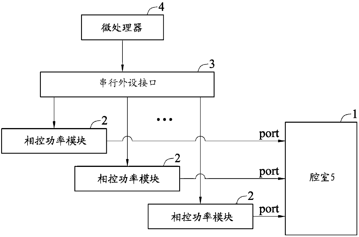
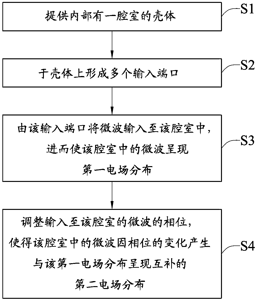
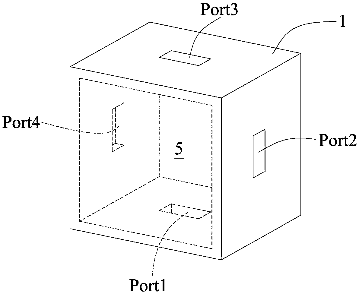
The invention discloses a distributed microwave phase control method, which comprises the following steps that a plurality of phase control power modules input microwaves into a cavity through each input port, so that the microwaves in the cavity are distributed in a first electric field; and each phase control power module adjusts the phase of the microwaves input into the cavity by each input port, so that the microwaves in the cavity generate second electric field distribution complementary to the first electric field distribution due to the change of the phase.

Description

technical field [0001] The invention relates to microwave control technology, in particular to a distributed microwave phase control method. Background technique [0002] The traditional microwave heating technology uses the magnetron to generate microwaves to heat the object to be heated. However, the distribution of the electric field strength of the microwave in this heating method is prone to unevenness, so that the part of the object to be heated located in the weak electric field area will suffer due to the weaker absorption intensity. A weak electric field produces a low heating area without significant heating, while the part of the heated object located in the strong electric field area will produce a high heating area that is significantly heated due to the strong electric field absorption intensity, thus causing the heated object to form after being heated by microwaves. The condition of uneven heating. [0003] In addition, in order to increase the temperature o...

Claims


Application Information

Patent Timeline
IPC IPC(8): H05B6/64H05B6/68
CPCH05B6/64H05B6/68
Inventor 黄家靖蔡岳霖陈叡宏
Owner IND TECH RES INST
Why Eureka
Try Eureka