
Fresh air device and control method thereof

A fresh air device and control method technology, applied in the direction of selection device, separation method, chemical instrument and method, etc., can solve the problems of shortened service life, dust easily suspended and scattered in the surrounding space, complex structure, etc., to reduce refrigeration The effect of duration

Pending Publication Date: 2020-07-03
GUANGDONG HIWAVE TECH
View PDF1 Cites 0 Cited by
  • Summary
  • Abstract
  • Description
  • Claims
  • Application Information

AI Technical Summary

Problems solved by technology

[0003] However, the existing fresh air device has a large volume, which is not conducive to installation
Moreover, as the application number: CN201120349171.7 discloses a fresh air system dust removal device, the automatic dust removal device of the existing fresh air system includes a bracket, a motor and a dust removal brush, etc., and its structure is complex, and when cooling, it is necessary to start the air intake fan to fill the room. For fresh air, when removing dust, start the intake fan to rotate in reverse to blow towards the filter, and at the same time start the dust removal brush to clean the filter. When the dust removal brush is started to clean the filter, the dust is easily suspended and scattered in the surrounding space. At this time, if the turning direction of the intake fan is restored to refill the room with fresh air, the scattered dust will be brought into the room, which will be harmful Indoor cleanliness will easily lead to clogging of the filter screen, resulting in poor cooling effect, and it will also increase its maintenance frequency, shorten its service life, and is not conducive to energy saving

Method used


Image

  • Fresh air device and control method thereof
  • Fresh air device and control method thereof
  • Fresh air device and control method thereof

Examples


Embodiment Construction

[0030] In order to make the above objects, features and advantages of the present invention more comprehensible, the present invention will be further described in detail below in conjunction with the accompanying drawings and specific embodiments.

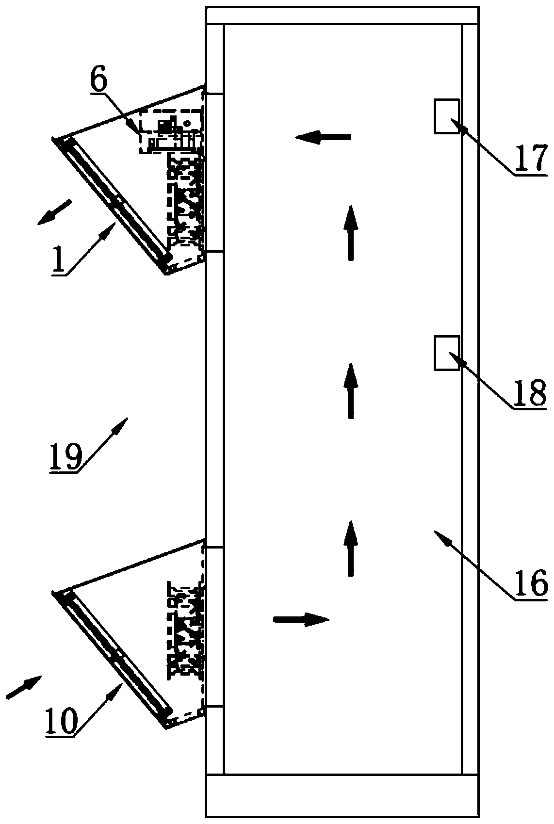
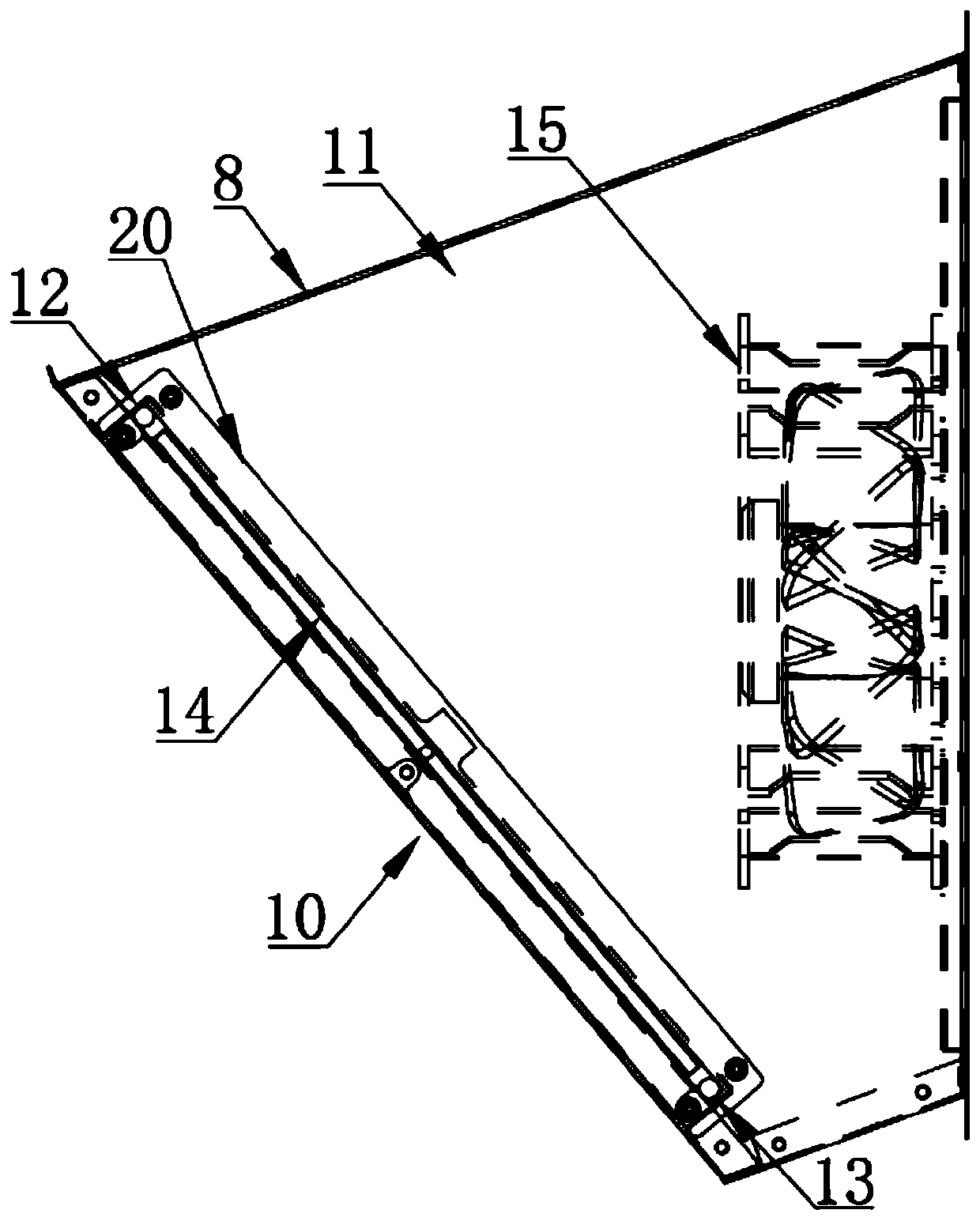
[0031] A kind of fresh air device of the present invention, with reference to Figure 1-3 , including an exhaust unit 1 and a dust removal unit 10. Wherein, the ventilation unit 1 and the dust removal unit 10 are all installed outdoors 19, so that the fresh air device does not occupy the interior space of the cabinet or machine room, which can reduce its transformation cost, and the fresh air device has strong versatility.

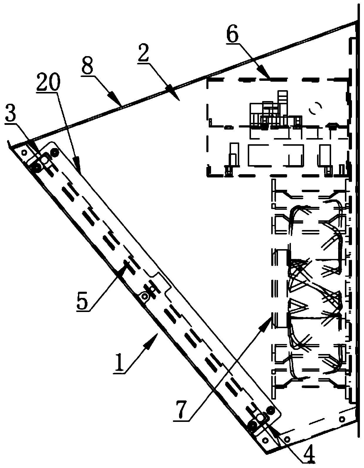
[0032] Wherein, the exhaust unit 1 includes a first cover body 2, a first filter screen 5, a controller 6 and an exhaust fan 7 electrically connected to the controller 6. The air outlet and the air outlet, the first filter screen 5 and the exhaust fan 7 are installed on the air outlet end and the air inlet en...


PUM


Abstract

The invention provides a fresh air device and a control method thereof. The fresh air device comprises an air draft unit and a dust removal unit. The air draft unit comprises a first cover body, a first filter screen, a controller and an air draft fan electrically connected with the controller, and the first cover body is provided with an air inlet and an air outlet which communicate with the interior and the exterior correspondingly. The dust removal unit comprises a second cover body, a second filter screen and a dust removal fan electrically connected with the controller. The second cover body is provided with an air outlet and an air inlet which are respectively communicated with the indoor and outdoor. During cooling, the air draft fan is started to exhaust indoor air to the outside from the first cover body, so that outdoor cold air is sucked into the indoor space through the second cover body. During dust removal, the dust removal fan is started and blows air to the second filter screen so as to remove dust on the surface of the second filter screen. According to the fresh air device, automatic dust removal can be achieved without additionally arranging a dust removal brush,the dust removal effect is good, the maintenance time and the service life of the fresh air device can be prolonged, and the energy-saving and cooling effects are good.

Description

technical field [0001] The invention relates to the technical field of fresh air cooling, in particular to a fresh air device and a control method thereof. Background technique [0002] In order to reduce cooling energy consumption and meet cooling needs, people gradually apply fresh air systems to cabinets and equipment rooms of base stations. The existing fresh air system consists of three components: a controller, an air intake unit (including an intake fan, a filter screen and an automatic dust removal device) and an exhaust unit (including an exhaust fan). The controller controls the intake fan to deliver low-temperature fresh air to the room. Then control the exhaust fan to discharge high-temperature air to the outside to form a fresh air flow field indoors, thereby achieving the purpose of cooling. The existing fresh air system has the advantages of energy saving and high utilization efficiency. [0003] However, the existing fresh air device has a large volume, whic...

Claims


Application Information

Patent Timeline
IPC IPC(8): H05K7/20H04Q1/02B01D46/10B01D46/00
CPCH05K7/20136H05K7/20145H05K7/20209H04Q1/035B01D46/10B01D46/71
Inventor 林浩东王水平张立锋黄小巧马智祥
Owner GUANGDONG HIWAVE TECH
Learn More