
Apparatus and method for improved processing of PVC

Inactive Publication Date: 2003-03-27
LITTLEFORD DAY
View PDF0 Cites 1 Cited by
  • Summary
  • Abstract
  • Description
  • Claims
  • Application Information

AI Technical Summary

Benefits of technology

[0011] More specifically, it is an objective to reduce the batch cooling time to improve the throughput rate of a cooler or cooling unit.

Problems solved by technology

Increasing the rotational speed of the tools does not necessarily provide more rapid cooling, however, because the mixing and sweeping action of the tools introduces energy, and therefore heat, into the process.
The inventors have found that the increased heat energy from high rotation speeds limits the cooling benefit gained in existing prior art PVC coolers.
A further drawback with existing PVC coolers is that a boundary layer of PVC builds up between the inner cooling surface and the tools due to mechanical tolerances.
This boundary layer at the cooling surface hinders the overall cooling process and the heat transfer at the inner chamber surface.
The PVC becomes compacted in the clearance space and forms an insulative boundary layer which hinders the heat transfer at the surface and thus hinders cooling of the PVC resin.

Method used


Image

  • Apparatus and method for improved processing of PVC
  • Apparatus and method for improved processing of PVC
  • Apparatus and method for improved processing of PVC

Examples


Embodiment Construction

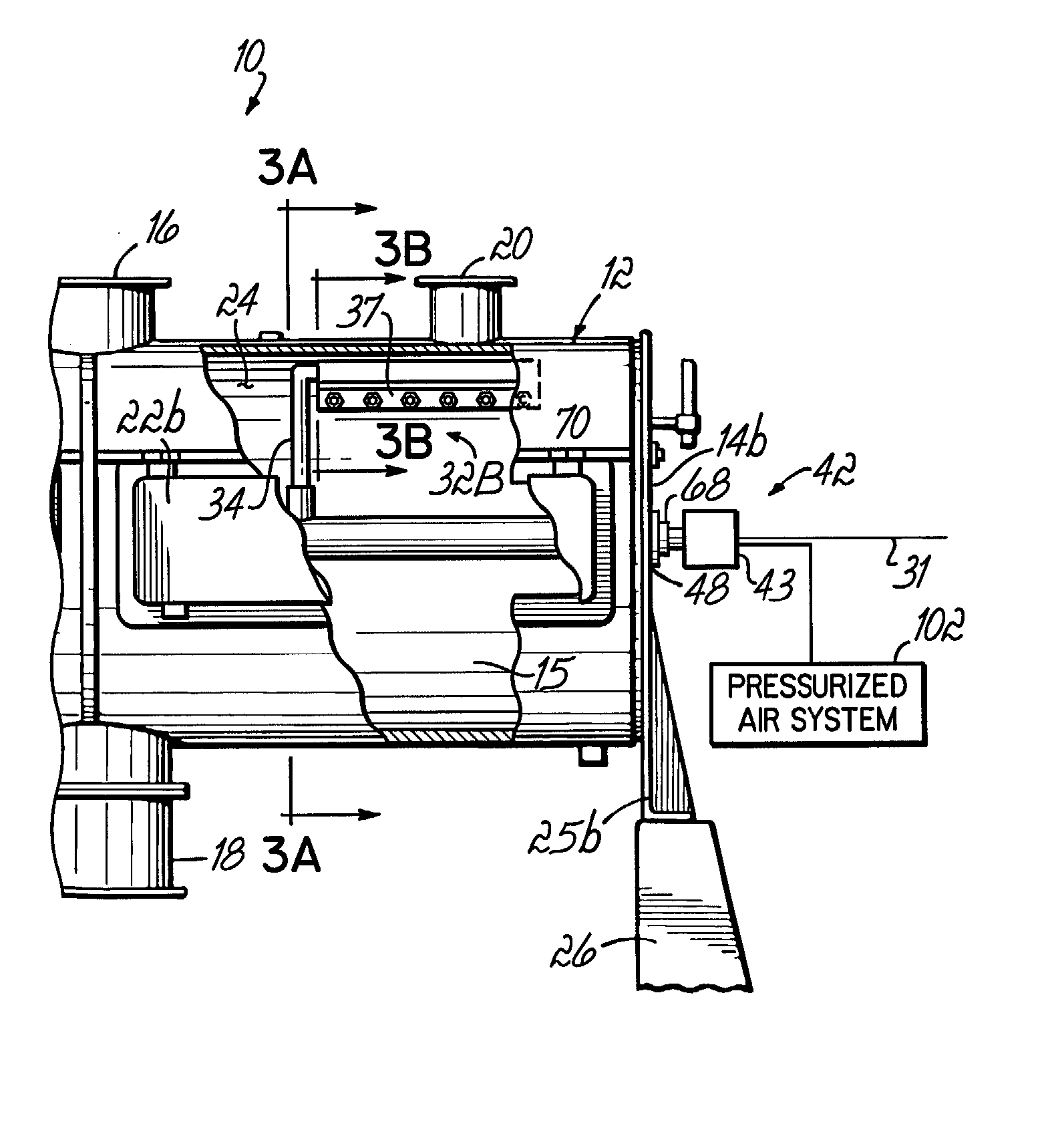
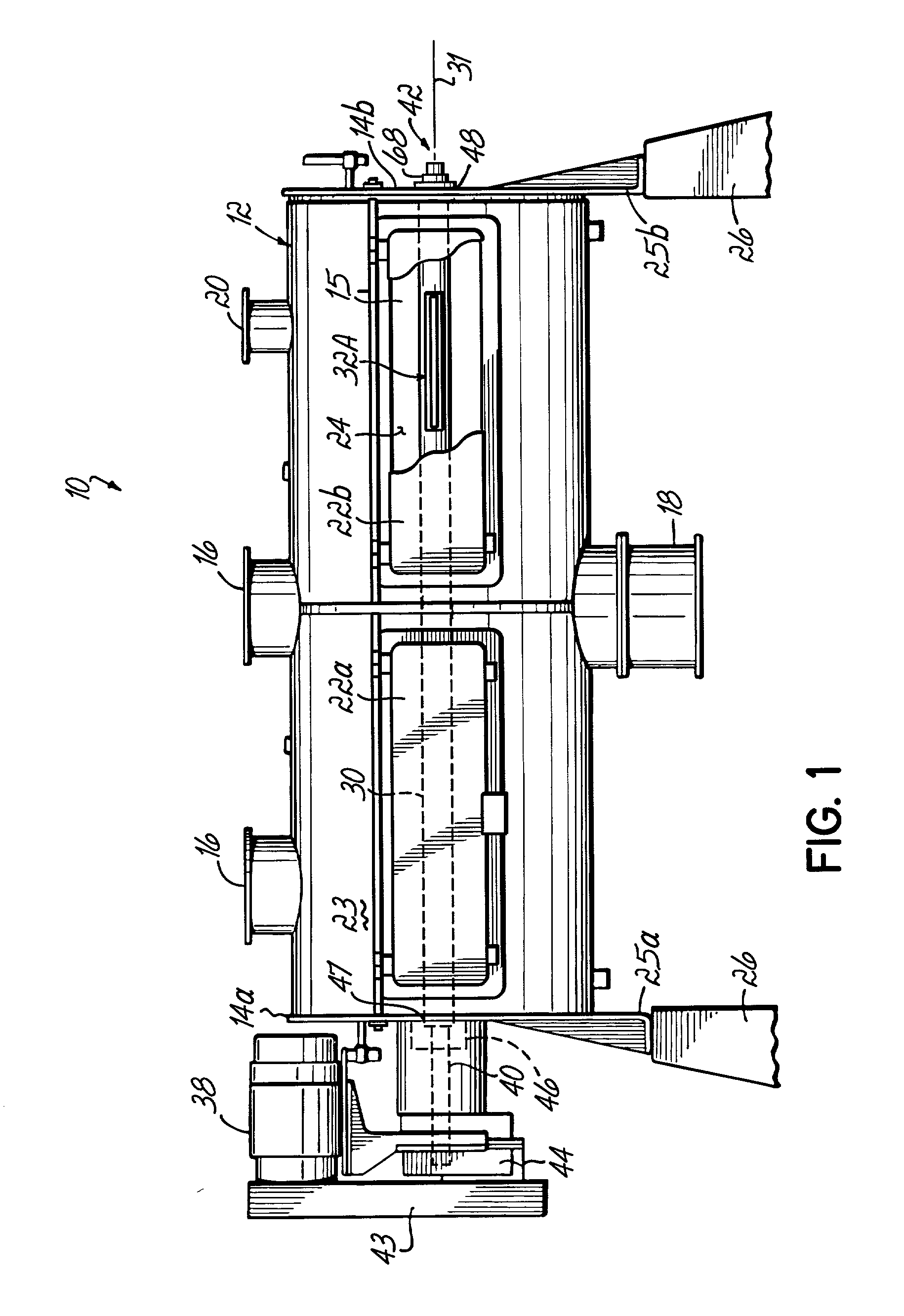
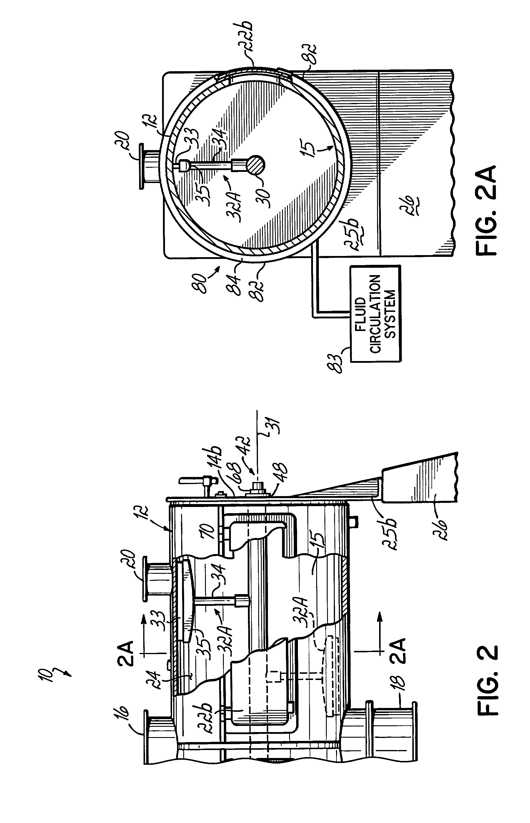
[0029] FIG. 1 illustrates a cooling unit or cooler 10 constructed in accordance with the principles of the present invention. The features of the invention may be used with various different types and embodiments of coolers, and the cooler 10 illustrates only one such embodiment. For example, the Model K Series of coolers from Littleford Day, Inc. may be equipped in accordance with the invention. The embodiment of the cooler 10 illustrated in FIG. 1 comprises a generally cylindrical and elongated chamber 12 which is horizontally disposed and is configured to receive therein materials which are to be cooled, such as compounded PVC material, for example. Of course, other materials might also be cooled in accordance with the invention. The mixing chamber 12 has a generally cylindrically-shaped side wall and opposing end walls or head walls 14a, 14b which close the ends of the chamber to contain the batch of material or compound. The chamber might be a double-walled or jacketed chamber ...


PUM

PropertyMeasurementUnit
Pressureaaaaaaaaaa
Angular velocityaaaaaaaaaa
Flexibilityaaaaaaaaaa

Abstract

An apparatus for cooling material, such as a PVC compound, includes a chamber having an inner surface and an inner space configured for receiving material to be cooled. A rotatable shaft extends through the chamber inner space, and is operable for being rotated by a motor. At least one mixing tool is coupled to the shaft to rotate with the shaft, and mix the material while rotating around the inner surface of the chamber so the material contacts the inner surface to be cooled thereby. In one embodiment, the mixing tool includes a flexible blade configured for contacting the chamber inner surface and for sweeping across a portion of the inner surface to dislodge an amount of material from the surface portion. Another embodiment utilizes an air knife to dislodge material from the inner chamber surface. The motor is operable for rotating the shaft at a speed in the range of 150 to 250 rpm to sweep the material from the inner surface.

Description

[0001] This invention is directed generally to an apparatus and method for cooling materials, and specifically to cooling a PVC compound.BACKGROUND OF INVENTION[0002] Polyvinyl chloride, or PVC, is a well known chemical material which has widespread use in the manufacturing of various products, such as pipes, containers, and a large number of other products. In utilizing PVC in the manufacturing process, the PVC is often supplied and handled in bulk form as a loose powder or resin. The bulk material is subsequently heated to a melting point and molded into a finished product, such as through an injection molding process, for example.[0003] Before being utilized in the molding process, raw PVC resin, must be mixed or compounded with other materials desirable for the particular product to be made or the particular end use of the PVC. For example, the raw PVC resin can be mixed with plasticizers, stabilizers, lubricants, and even pigments, such as for adding color to the PVC. Such comp...

Claims


Application Information

Patent Timeline
IPC IPC(8): B29B13/04
CPCB29B13/045B29K2027/06
Inventor KESIG, RICKY D.DZIECH, COREY L.
Owner LITTLEFORD DAY
Learn More