Automatic cake dicing equipment
A technology for cutting cakes and cakes, which is applied in the field of automatic cake cutting equipment, and can solve problems such as difficulty in cutting cakes evenly and inconvenient take-out
- Summary
- Abstract
- Description
- Claims
- Application Information
AI Technical Summary
Problems solved by technology
Method used
Image
Examples
Embodiment 1
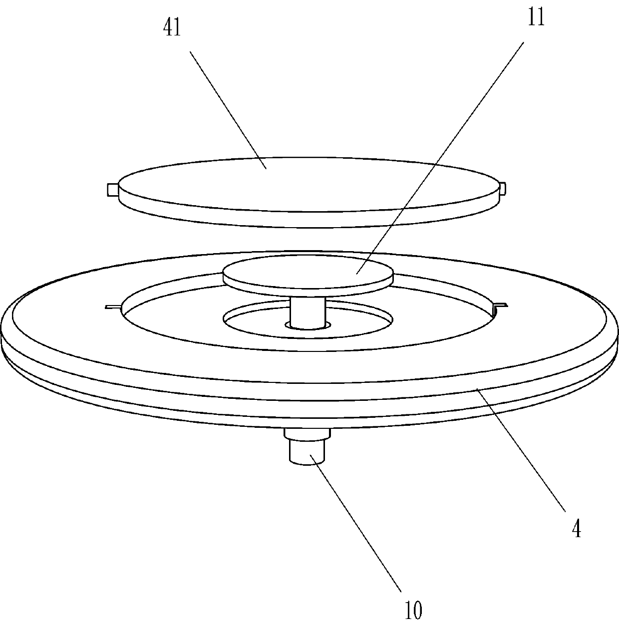
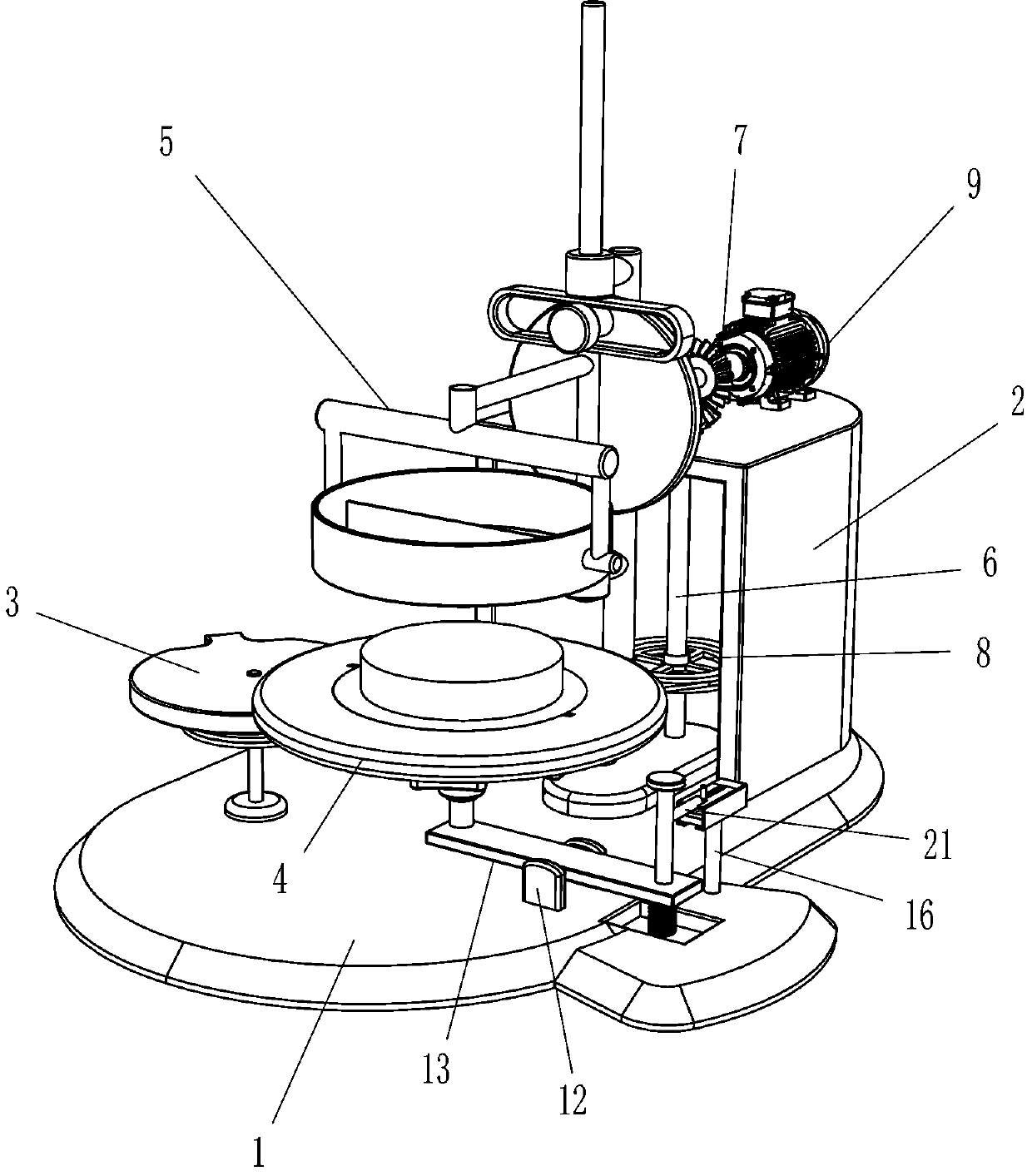
[0024] Such as Figure 1-4 and Figure 6 As shown, it includes a base 1, a mounting frame 2, a steering mechanism 3, a work plate 4, a placement plate 41, a cutting mechanism 5, a rotating rod 6, a bevel gear 7, a belt transmission mechanism 8 and a servo motor 9, and the right side of the base 1 is There is a mounting frame 2, a steering mechanism 3 is provided on the upper left side of the base 1, and a working disk 4 is fixedly connected to the upper part of the front side of the steering mechanism 3. There is a circular groove on the top of the working disk 4, and a placement disk is placed in the circular groove 41. The upper middle part of the base 1 is provided with a cutting mechanism 5, the cutting mechanism 5 is located between the mounting frame 2 and the steering mechanism 3, and the right side of the base 1 is provided with a rotating rod 6, which is located inside the mounting frame 2, and the rotating rod The upper part of 6 passes through the upper part of the...
Embodiment 2
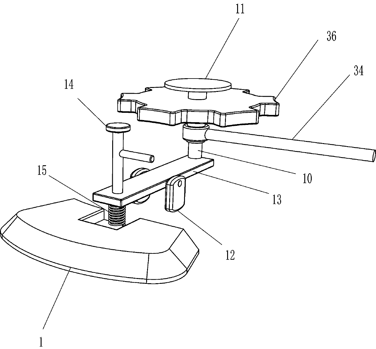
[0031] On the basis of Example 1, such as figure 1 and Figure 4-6 As shown, it also includes a moving rod 10, a top plate 11, a mounting seat 12, a swing plate 13, a pressing rod 14 and a first elastic member 15, and the sliding type of the second rotating shaft 35 is provided with a moving rod 10, and the top end of the moving rod 10 is provided with a moving rod 10. There is a top plate 11, and the top plate 11 is in contact with the placement plate 41. On the left front side of the base 1, there are mounting seats 12 symmetrically arranged on the left and right. A swinging plate 13 is installed between the mounting seats 12, and the top of the rear side of the swinging plate 13 is connected to the moving rod. The bottom end of 10 is in contact with each other, and the top of the front side of the swing plate 13 is provided with a pressing rod 14 .
[0032] Also include support rod 16, chute box 17, second elastic member 18, wedge block 19, pull bar 20 and clamping rod 21,...
PUM
 Abstract
Description
Claims
Application Information
 - R&D
- Intellectual Property
- Life Sciences
- Materials
- Tech Scout
- Unparalleled Data Quality
- Higher Quality Content
- 60% Fewer Hallucinations
Browse by: Latest US Patents, China's latest patents, Technical Efficacy Thesaurus, Application Domain, Technology Topic, Popular Technical Reports.
© 2025 PatSnap. All rights reserved.Legal|Privacy policy|Modern Slavery Act Transparency Statement|Sitemap|About US| Contact US: help@patsnap.com


