
Scanning bracket of medical imaging system

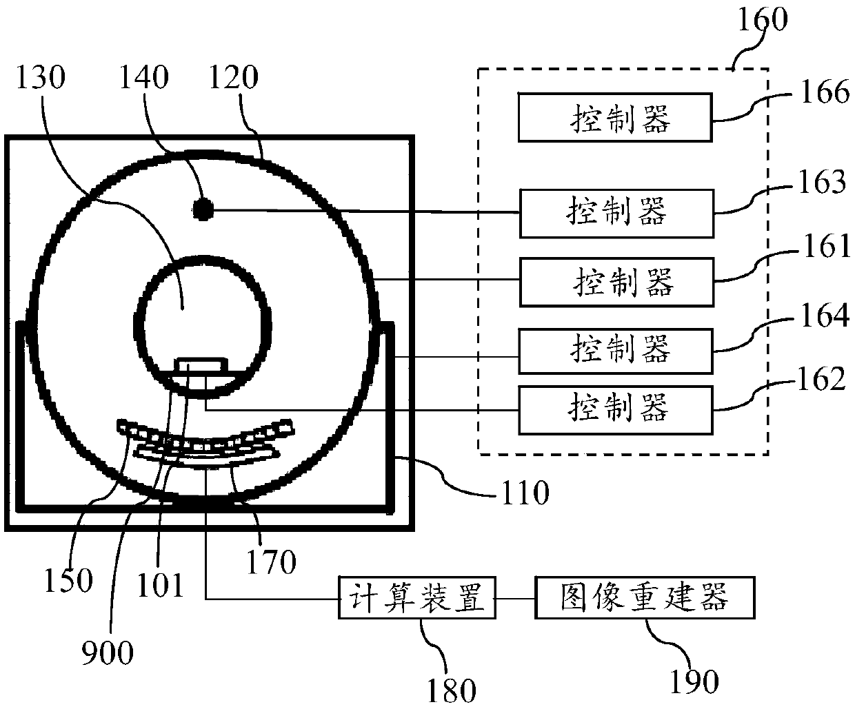
A technology for scanning stents and medical imaging, applied in the field of scanning stents of medical imaging systems, and can solve problems such as limiting rotation speed

Pending Publication Date: 2020-07-07
GENERAL ELECTRIC CO
View PDF0 Cites 4 Cited by
  • Summary
  • Abstract
  • Description
  • Claims
  • Application Information

AI Technical Summary

Problems solved by technology

[0003] With the continuous development of imaging technology, in some applications, the rotatable parts also need to be able to tilt, for example, to adapt to special imaging angles and / or reduce the radiation dose applied to the object, so the rotatable parts need to be tilted High-speed rotation is used to realize the imaging process. Currently, when the rotating part rotates, the vibration amplitude of the rotating part on the scanning bracket with tilt function limits the further improvement of the rotating speed.

Method used


Image

  • Scanning bracket of medical imaging system
  • Scanning bracket of medical imaging system
  • Scanning bracket of medical imaging system

Examples


Embodiment Construction

[0033] Specific implementations of the present invention will be described below. It should be noted that in the process of specific descriptions of these implementations, for the sake of concise description, it is impossible for this specification to describe all the features of the actual implementations in detail. It should be understood that, in the actual implementation process of any embodiment, just like in the process of any engineering project or design project, in order to achieve the developer's specific goals and to meet system-related or business-related constraints, Often a variety of specific decisions are made, and this can vary from one implementation to another. In addition, it will be appreciated that while such development efforts may be complex and lengthy, the technology disclosed in this disclosure will be Some design, manufacturing or production changes based on the content are just conventional technical means, and should not be interpreted as insuffic...


PUM


Abstract

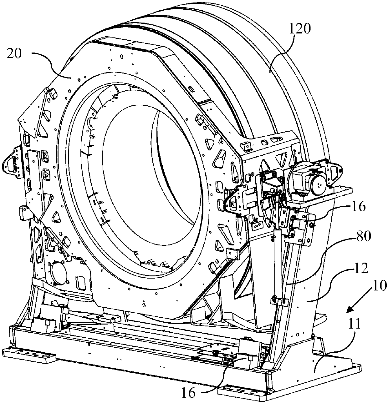
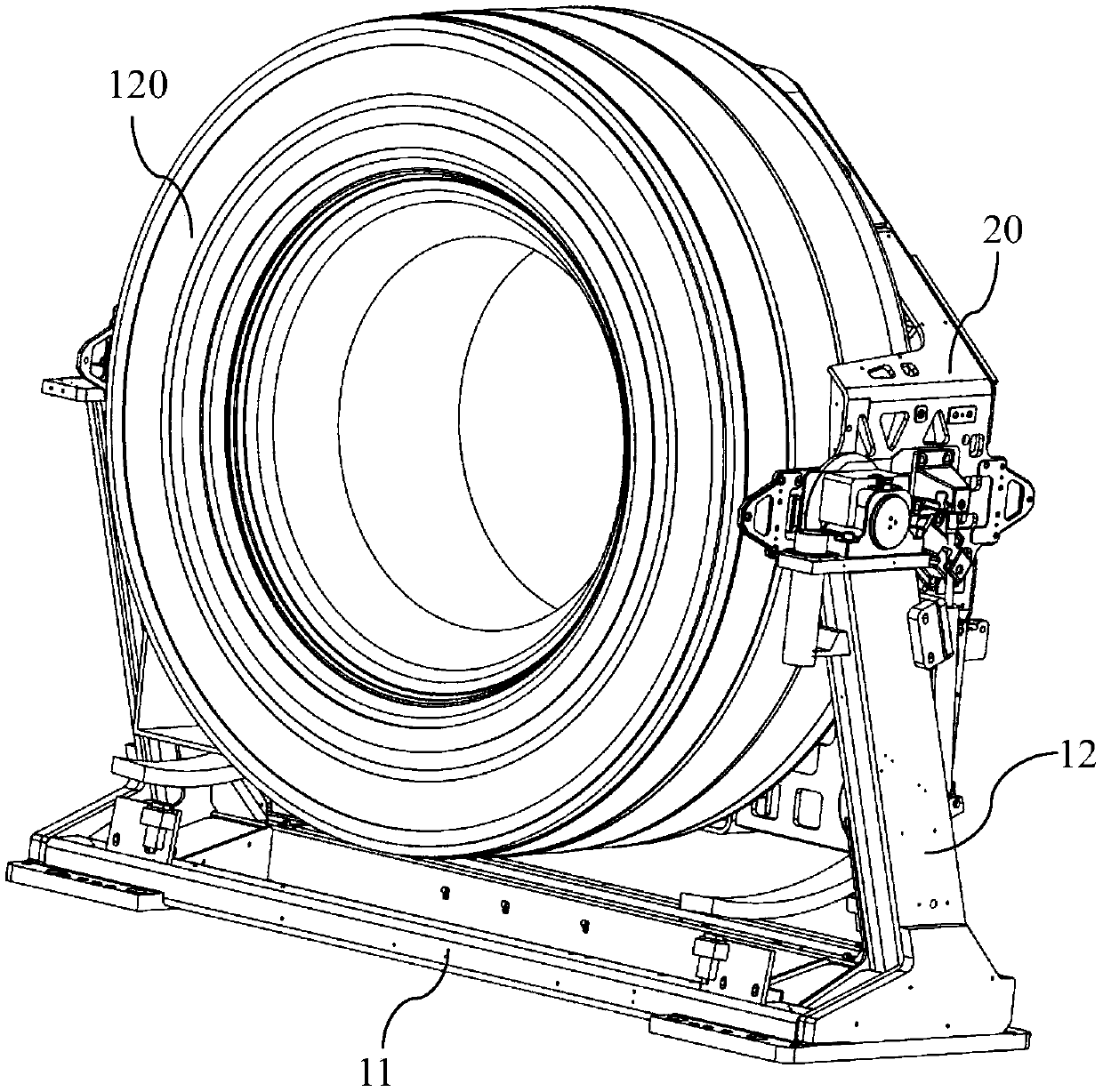
The invention provides a scanning bracket for a medical imaging system. The scanning bracket comprises a bottom support frame and a tilt support frame connected to each other, and the tilt support frame can be tilted relative to the bottom support frame. The scanning bracket also comprises a locking mechanism connected between the bottom support frame and the tilt support frame, and the locking mechanism is in an unlocked state during the tilting of the tilt support frame relative to the bottom support frame; and the locking mechanism is in a locked state when the tilt support frame is stationary relative to the bottom support frame, so as to prevent the tilt support frame from moving relative to the bottom support frame.

Description

technical field [0001] The invention relates to the field of medical imaging, in particular to a scanning support for a medical imaging system. Background technique [0002] A medical imaging system, such as a computed tomography (CT) system, has a scanning support. The scanning support generally includes a base and a rotatable part arranged on the base. The rotatable part is provided with imaging components such as X-ray tubes and detectors. By driving these components to rotate at a high speed, the three-dimensional imaging of the object in the scanning cavity located in the middle of the rotatable component is realized. [0003] With the continuous development of imaging technology, in some applications, the rotatable parts also need to be able to tilt, for example, to adapt to special imaging angles and / or reduce the radiation dose applied to the object, so the rotatable parts need to be tilted High-speed rotation is used to realize the imaging process. Currently, when ...

Claims


Application Information

Patent Timeline
Patent Type & Authority Applications(China)
IPC IPC(8): A61B6/03
CPCA61B6/032A61B6/4435A61B6/4447A61B6/035A61B6/105
Inventor 张笑妍杨绪勇郭军
Owner GENERAL ELECTRIC CO
Learn More