An improved design method for error-prone riveting of server sheet metal parts

A technology of sheet metal parts and design methods, which is applied in the field of sheet metal riveting processing, can solve problems such as easy riveting of hardware parts, low cost, and wrong riveting of hardware parts, and achieve the goal of improving product yield and good intangible benefits Effect

Active Publication Date: 2022-03-15
INSPUR SUZHOU INTELLIGENT TECH CO LTD
View PDF0 Cites 0 Cited by
  • Summary
  • Abstract
  • Description
  • Claims
  • Application Information

AI Technical Summary

Problems solved by technology

[0007] In view of the above problems, the present invention provides an improved design method for error-riveting hardware of server sheet metal parts. This solution can effectively solve the problem of hardware error riveting, and only requires a small investment

Method used


Image

  • An improved design method for error-prone riveting of server sheet metal parts
  • An improved design method for error-prone riveting of server sheet metal parts
  • An improved design method for error-prone riveting of server sheet metal parts

Examples


Embodiment 1

[0036] Through the analysis of the technical problems in the background technology, it can be known, such as Figure 5 As shown, the wrong riveting situation is mainly caused by misplacement of the small hardware 4 into the hole of the large hardware, because the large hardware 4 cannot be put into the small hole.

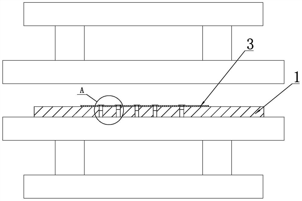
[0037] For this, as Figure 6 and Figure 7 As shown, the lower template 1 of the stamping equipment is provided with a height-limiting block 2 matching with the installation hardware 4 (that is, the type of the height-limiting block 2 corresponds to the type of the hardware 4 one by one), preferably, The height limiting block 2 is cylindrical, and the lower template 1 is provided with a cylindrical groove for accommodating the height limiting block 2, and when the height limiting block 2 is placed in the groove When inside, the upper end surface of the height limiting block 2 is flush with the upper side of the lower formwork 1 . An insertion hole 21 extending ...

Embodiment 2

[0047] Generally speaking, the function of the hardware 4 is the thread and height. The thread is related to the inner diameter of the hardware 4, and the outer diameter of the hardware 4 generally has little effect on the function of the product 3 and can be adjusted. Therefore, it can be adjusted according to the actual situation in the design. If it is necessary to adjust the outer diameter of the hardware, the outer diameter of the short hardware 4 is designed to be large.

[0048] Product 3 Structural optimization Although the outer diameter of hardware 4 can be realized in most cases, there are also special cases, such as when the outer diameter and height of hardware 4 have functions at the same time, the outer diameter cannot be adjusted casually.

[0049] According to the stamping experience of iron parts, the opening size of the lower die hole of the metal riveting die is determined by the root diameter of the hardware, and if the outer diameter of the hardware 4 in p...

Embodiment 3

[0054] The hardware 4 installed on the lower formwork 1 is named as the first type of hardware, the second type of hardware . . .

[0055] As a specific implementation, there are three types of hardware on the lower formwork 1 described in this embodiment, and they are the first type of hardware and the second type of hardware according to the order of the diameter of the end portion 42 from small to large. and the third category of hardware.

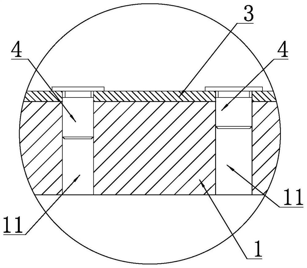
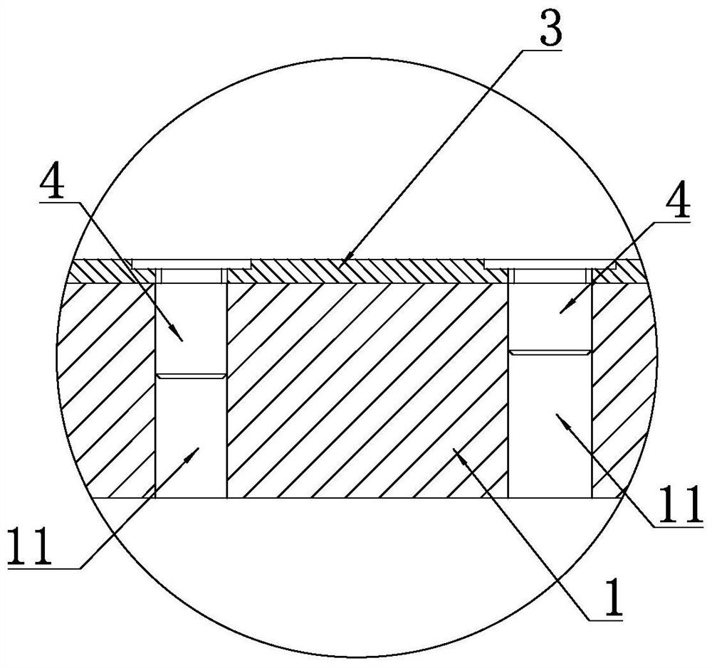
[0056] The lower template 1 is provided with through holes 11 corresponding to the first type of hardware and height limiting blocks 2 respectively corresponding to the second type of hardware and the third type of hardware.

[0057] All the other structures are the same as in Embodiment 1.


PUM

PropertyMeasurementUnit
diameteraaaaaaaaaa
thicknessaaaaaaaaaa

Abstract

The invention discloses an improved design method for error-prone riveting of metal parts of server sheet metal parts, and relates to the technical field of riveting processing of sheet metal parts. Specifically, the lower formwork of the stamping equipment is provided with a height-limiting block matched with mounting hardware, and when the height-limiting block is installed on the lower formwork, the upper end surface of the height-limiting block is in contact with the height-limiting block. The upper side of the template below is flush. An insertion hole extending downward is provided on the upper end surface of the height limiting block. The sum of the lengths of the ends of the hardware and the lengths of the transition connection parts increases sequentially in the order of end diameters from large to small, and when the hardware is misplaced into the insertion hole, the hardware is in the jacked up state. The invention can solve the problem that different types of hardware are easy to be wrongly riveted in mass production and processing. As long as the mass production and processing of the mold is used, it can be improved through this solution. Through the optimization of the structural design and the improvement of the mold, it can achieve 100% foolproof. It is especially suitable for server products with moderate production volume.

Description

technical field [0001] The invention relates to the technical field of pressure riveting processing of sheet metal parts, in particular to an improved design method for error-prone riveting of server sheet metal parts. Background technique [0002] There are many pieces of iron and gold products that require riveting hardware, such as the studs for locking the main board of the machine base, the I-shaped hardware for the upper cover to be inserted into the base, the positioning pin hardware for the upper cover to be inserted into the rear window, and so on. [0003] In order to facilitate the understanding of this program, a brief description of the riveting processing method is now given. Such as figure 1 and figure 2 As shown, the so-called pressure riveting first needs to place the product to be processed on the lower template of the pressure riveting equipment, and then put the hardware into the through hole that has been pre-processed on the product. Correspondingly,...

Claims


Application Information

Patent Timeline
Patent Type & Authority Patents(China)
IPC IPC(8): B21D37/10B21D39/00B21C51/00
CPCB21D37/10B21D39/00B21C51/00
Inventor 温建福
Owner INSPUR SUZHOU INTELLIGENT TECH CO LTD
Why Eureka
Try Eureka