Lug plate machining clamp

A lug and fixture technology, applied in the direction of manufacturing tools, metal processing equipment, metal processing mechanical parts, etc., can solve the problems of large errors in the drilled holes, easy to move, affecting the use effect, etc., and achieves good limit effect and operation. Simple and convenient, good processing quality

Inactive Publication Date: 2016-08-03
CHANGXING QIKAI MECHANICAL EQUIP CO LTD
View PDF7 Cites 0 Cited by
  • Summary
  • Abstract
  • Description
  • Claims
  • Application Information

AI Technical Summary

Problems solved by technology

Since it is necessary to process multiple through holes on the ear plate, the usual method is to use a drill to drill through holes on it. When drilling, the ear plate is subject to a large force and is easy to move, resulting in the error of the drilled hole. Larger, affecting its use effect

Method used


Image

  • Lug plate machining clamp
  • Lug plate machining clamp
  • Lug plate machining clamp

Examples


Embodiment 1

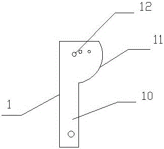
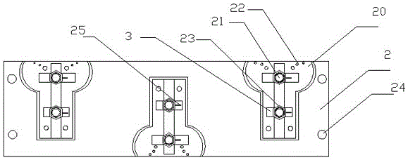
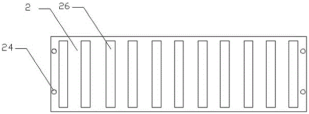
[0028] This embodiment includes a base plate 2 and a limiting plate 3. A groove 20 adapted to the shape of the ear plate 11 is arranged on the base plate 2. A plurality of blind holes 22 are also arranged in the groove 20. The blind holes 22 The size and position are the same as the size and position of the through hole on the lug plate 1. A limit post 21 is arranged on one side of the groove 20. The limit post 21 is perpendicular to the base plate. The limit post 21 is provided with threads, and the limit plate is set There is a hole, the diameter of which is larger than the diameter of the limiting post 21 , the limiting post 21 is equipped with a limiting nut 23 , and the limiting plate is limited on the limiting post 21 by the limiting nut 23 . Through the cooperation of the groove 20 and the limit plate, the ear plate 1 can be firmly limited on the base plate, and the ear plate 1 will not move when processing the through holes on the ear plate 1, and there will be no proce...

Embodiment 2

[0030] This embodiment includes a base plate 2 and a limiting plate 3. Two grooves 20 adapted to the shape of the ear plate 11 are arranged on the base plate 2, and a plurality of blind holes 22 are also arranged in the grooves 20. The blind holes 22 The size and position of the hole are the same as the size and position of the through hole on the ear plate 1. On one side of the groove 20, a limit column 21 is arranged. The limit column 21 is perpendicular to the base plate. The limit column 21 is provided with threads, and the limit plate A hole is provided, and the diameter of the hole is larger than the diameter of the limit post 21. The limit post 21 is equipped with a limit nut 23, and the limit plate is limited on the limit post 21 by the limit nut 23. Through the cooperation of the groove 20 and the limit plate, the ear plate 1 can be firmly limited on the base plate, and the ear plate 1 will not move when processing the through holes on the ear plate 1, and there will b...

Embodiment 3

[0033] This embodiment includes a base plate 2 and a limiting plate 3. Four grooves 20 adapted to the shape of the lug plate 11 are arranged on the base plate 2, and a plurality of blind holes 22 are also arranged in the grooves 20. The blind holes 22 The size and position of the hole are the same as the size and position of the through hole on the ear plate 1. On one side of the groove 20, a limit column 21 is arranged. The limit column 21 is perpendicular to the base plate. The limit column 21 is provided with threads, and the limit plate A hole is provided, and the diameter of the hole is larger than the diameter of the limit post 21. The limit post 21 is equipped with a limit nut 23, and the limit plate is limited on the limit post 21 by the limit nut 23. Through the cooperation of the groove 20 and the limit plate, the ear plate 1 can be firmly limited on the base plate, and the ear plate 1 will not move when processing the through holes on the ear plate 1, and there will ...


PUM


Abstract

The invention discloses a lug plate machining clamp which comprises a base plate and limiting plates. At least one groove matched with the appearance of a lug plate is formed in the base plate. A plurality of blind holes are further formed in each groove. The size and positions of the blind holes are identical to the size and positions of through holes in the lug plate. A limiting groove column is arranged on one side of each groove and is perpendicular to the base plate, and threads are arranged on the limiting columns. The limiting plates are provided with holes, the aperture is larger than the diameter of the limiting columns, the limiting columns are provided with limiting nuts, and the limiting plates are limited on the limiting columns through the limiting nuts. In the machining process, the lug plate machining clamp cannot move, the error of the machined holes is small, and the requirements are completely met.

Description

technical field [0001] The invention relates to a processing jig, in particular to a processing jig for an ear plate 1 . Background technique [0002] Ear plate is a kind of auto parts, its structure is as follows figure 1 As shown, it mainly includes a rectangular plate 10 and a fan-shaped plate 11. The rectangular plate 10 and the fan-shaped plate 11 are integrally formed, and then some through holes 12 are distributed thereon. Since it is necessary to process multiple through holes on the ear plate, the usual method is to use a drill to drill through holes on it. When drilling, the ear plate is subject to a large force and is easy to move, resulting in the error of the drilled hole. Larger, affecting its use effect. Contents of the invention [0003] In order to overcome the deficiencies of the prior art, the present invention provides a jig for lug plate processing. The lug plate is limited and fixed by the action of the jig. During processing, the lug plate will not...

Claims


Application Information

Patent Timeline
IPC IPC(8): B23Q3/06
CPCB23Q3/062
Inventor 许胜强
Owner CHANGXING QIKAI MECHANICAL EQUIP CO LTD
Why Eureka
Try Eureka