Processed upper tool positioning method special for valve body

A positioning method and valve body technology, applied in metal processing, chucks, etc., can solve the problem of low processing accuracy of the connection end

Active Publication Date: 2020-07-07
惠州联合阀控液压技术有限公司
View PDF14 Cites 2 Cited by
  • Summary
  • Abstract
  • Description
  • Claims
  • Application Information

AI Technical Summary

Problems solved by technology

[0005] In view of the above problems, the present invention provides a special processing and positioning method for the valve body. In the process of grasping and fixing the valve body by the clamping mechanism through the centering step, the clamping step and the deviation correction step are used synchronously. The tightening claws and positioning claws h...

Method used


Image

  • Processed upper tool positioning method special for valve body
  • Processed upper tool positioning method special for valve body
  • Processed upper tool positioning method special for valve body

Examples


Embodiment 1

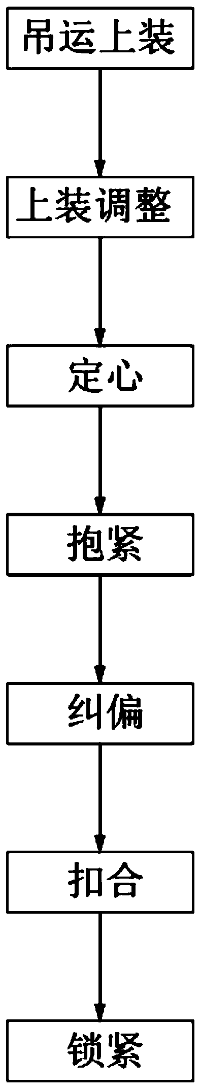
[0045] like figure 1 As shown, a method for positioning the upper part of the special processing of the valve body includes the following steps:

[0046] Step 1: hoisting and loading, hoisting the valve body 1 to be processed to the adjacent side of the installation vertical plate 3, the first port 13 at one end of the main body 11 on the valve body 1 is sleeved to the fixed mounting plate 3 The heart grasps the assembly 41;

[0047] Step 2, top-loading adjustment, after the valve body 1 is sleeved on the centering and grasping assembly 41, by rotating the valve body 1, the interface ends 12 on both sides of the main body 11 of the valve body 1 are placed on the installation On the corresponding clamping claw 511 on the clamping component 51 on the front side of the vertical plate 3;

[0048] Step 3, centering, the driving assembly 43 on the installation vertical plate 3 starts, drives the three-jaw chuck 411 on the centering and grasping assembly 41 to run, and makes the po...

Embodiment 2

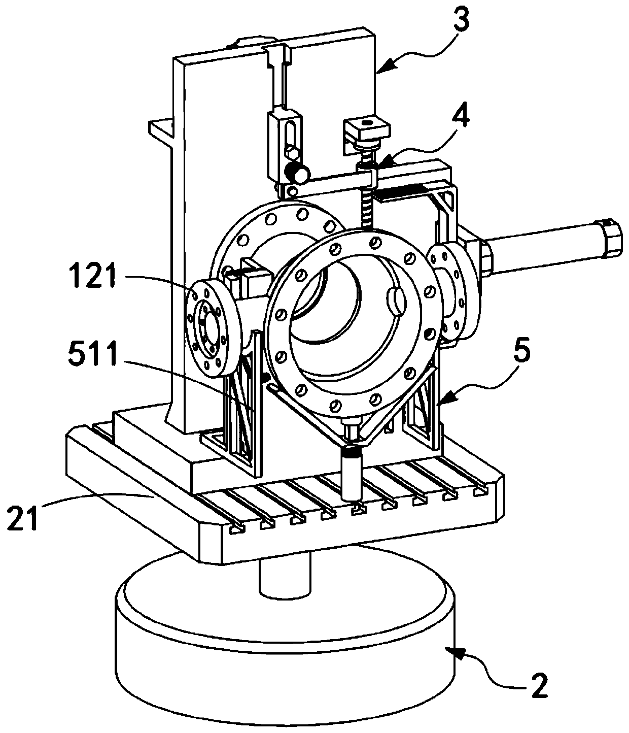
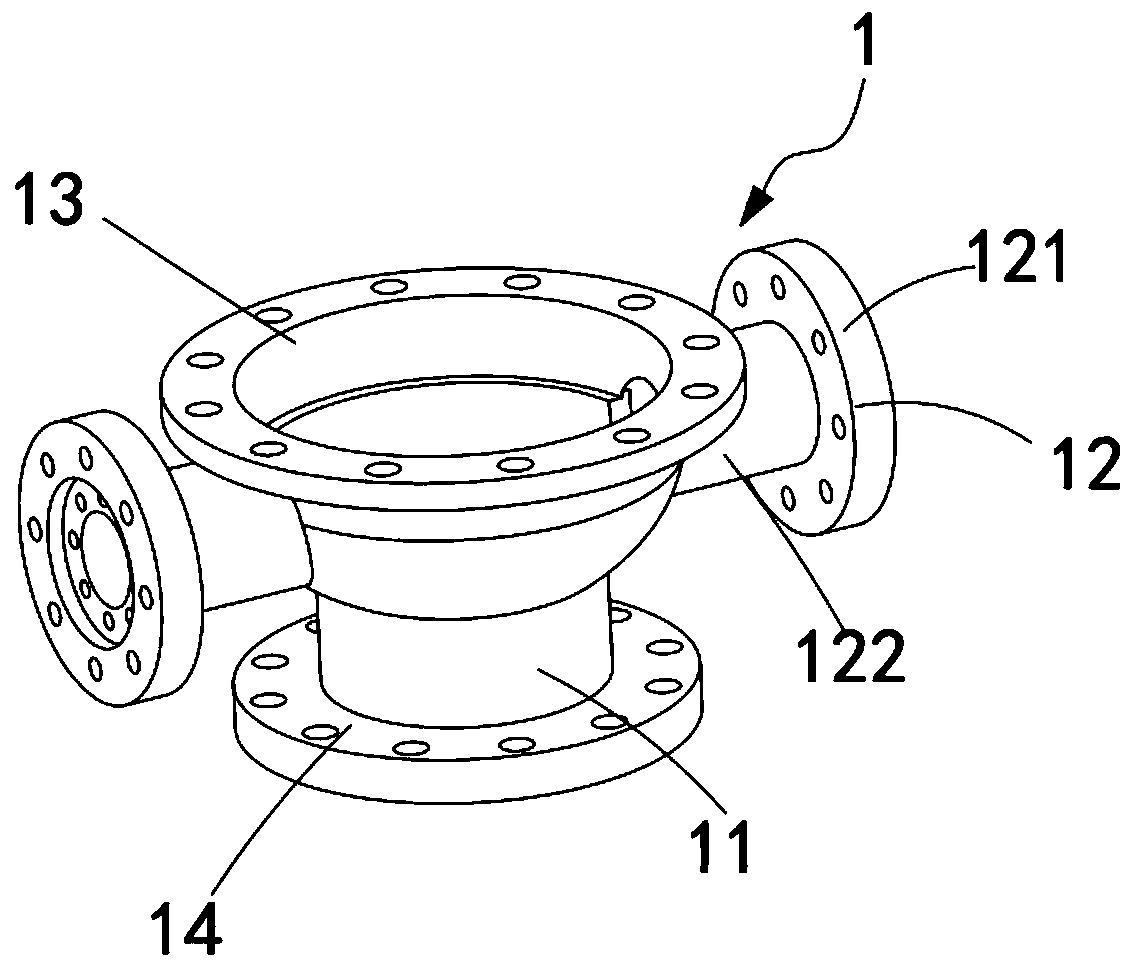
[0063] like Figure 2 to Figure 4 As shown in the figure, a valve body special machining and positioning method is used to fix the valve body 1 to be processed. The valve body 1 includes a main body 11 and an interface end 12 arranged perpendicularly to the main body 11. The interface end 12 is separately arranged on the main body. 11, the two ends of the main body 11 are respectively the first port 13 and the second port 14, including:

[0064] A rotating electrical machine 2, a mounting base 21 is installed on the rotating shaft of the rotating electrical machine 2;

[0065] Install the vertical board 3, the installation vertical board 3 is vertically installed on the installation base 21, the first port 13 of the valve body 1 is attached to the installation vertical board 3;

[0066] Clamping mechanism 4, the clamping mechanism 4 is installed on the described installation vertical plate 3, it is used for clamping and fixing the valve body 1 on the described installation ve...


PUM


Abstract

The invention relates to the technical field of valve processing, in particular to a processed upper tool positioning method special for a valve body. The processed upper tool positioning method comprises the steps of upper tool lifting and transporting, upper tool adjusting, centering, holding tightly, deviation correcting, buckling and locking. According to the processed upper tool positioning method, in the step of centering, an installation and clamping mechanism is utilized to clamp and fix the valve body, the steps of holding tightly and deviation correcting are synchronously utilized, connecting ends on the two sides of the valve body are tightly held and buckled by a holding claw and a positioning claw in a deviation correcting mechanism, thus the axis of a connecting end part is arranged horizontally, it is guaranteed that the flanging of the connecting end part is arranged vertically, the subsequent accurate processing is convenient, and the technical problem of low processing accuracy of the connecting end caused by clamping and fixing is solved.

Description

technical field [0001] The invention relates to the technical field of valve processing, in particular to a positioning method for valve body special-purpose processing. Background technique [0002] Before the valve body is processed, it needs to be locked and positioned by positioning tooling. However, due to the specific shape of the valve body, during the process of locking and positioning the valve body, it is very easy to cause the connecting ends on both sides of the valve body to be locked during the upper assembly process. , its axis cannot be kept horizontal, resulting in errors when turning or drilling the connection end. [0003] In the Chinese patent with the patent number CN201710561184.2, a fourth-axis rotary indexing processing device for a special machining center for pump covers is disclosed, including a rotary indexing component, which realizes the function of rotating and indexing the workpiece according to the preset angle requirements; The clamp body p...

Claims


Application Information

Patent Timeline
IPC IPC(8): B23Q7/00B23B31/103
CPCB23B31/103B23Q7/00
Inventor 钱俊周杰庄阳
Owner 惠州联合阀控液压技术有限公司
Why Eureka
Try Eureka