
Rapid bolt fastening device

A fastening device and fast technology, applied in the direction of hand-held tools, manufacturing tools, etc., can solve the problems of cumbersome operation process and unfavorable work efficiency

Inactive Publication Date: 2020-07-07
RES INST OF ECONOMICS & TECH STATE GRID SHANDONG ELECTRIC POWER +3
View PDF5 Cites 1 Cited by
  • Summary
  • Abstract
  • Description
  • Claims
  • Application Information

AI Technical Summary

Problems solved by technology

The operation process is cumbersome, which is not conducive to improving work efficiency

Method used


Image

  • Rapid bolt fastening device
  • Rapid bolt fastening device
  • Rapid bolt fastening device

Examples


Embodiment 1

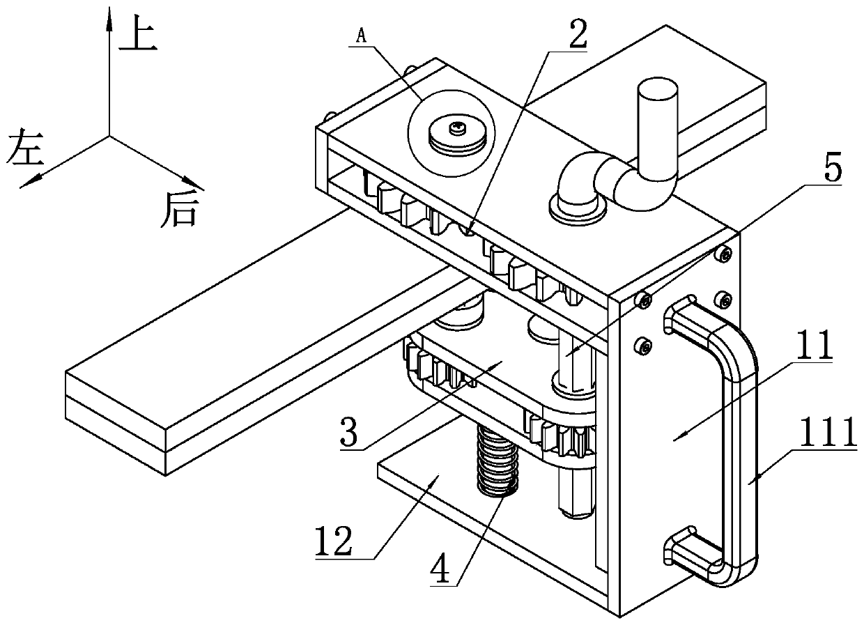
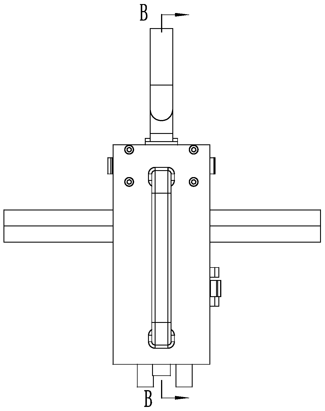
[0051] Such as figure 1 and image 3 As shown, a fast bolt fastening device includes a main frame body, the main frame body includes a riser 11, the lower end of the riser 11 is fixedly provided with a bottom plate 12 extending to the front side by welding, and the The above-mentioned riser 11 and bottom plate 12 jointly form an L-shaped structure.

[0052] An upper tightening unit 2 and a lower tightening unit 3 are sequentially arranged above the bottom plate 12 from top to bottom.

[0053] Such as figure 1 , Figure 6 and Figure 11 As shown, the upper screwing unit 2 sequentially includes a first upper horizontal plate 21 and a second upper horizontal plate 22 from top to bottom, and the rear ends of the first upper horizontal plate 21 and the second upper horizontal plate 22 They are respectively fixedly connected with the above-mentioned risers 11 by screws. Between the first upper horizontal plate 21 and the second upper horizontal plate 22, an upper driving gear ...

Embodiment 2

[0069] A connecting shaft is arranged between the first rotating shaft 241 and the third rotating shaft 331, and the upper end of the connecting shaft is fixedly connected with the first rotating shaft 241. The third rotating shaft 331 is provided with a through hole matched with the connecting shaft, the lower tightening unit can slide up and down along the connecting shaft, and the through hole is connected with the connecting shaft. The shaft cooperates to limit the relative rotation between the connecting shaft and the lower driving gear. A concave portion is disposed on the upper end surface of the first rotating shaft 241 . The top of the upper driving gear 24 is provided with a drive handle, the drive handle is L-shaped, and the suspended end of the horizontal part of the drive handle is provided with a raised portion matched with the concave portion, and the The cooperation between the above-mentioned recessed part and the raised part restricts the relative rotation b...

Embodiment 3

[0071] A connecting shaft is arranged between the first rotating shaft 241 and the third rotating shaft 331, and the upper and lower ends of the connecting shaft are fixedly connected to the first rotating shaft 241 and the third rotating shaft 331 respectively. The first upper horizontal plate 21 is provided with a motor mounting frame, and a torque motor is fixedly arranged on the motor mounting frame, the output shaft of the torque motor is fixedly connected with the first rotating shaft 241, and the rest of the structure is the same as Embodiment one.


PUM


Abstract

The invention discloses a rapid bolt fastening device, and relates to the technical field of thread fastening tools. The rapid bolt fastening device comprises a vertical plate, a bottom plate, an upper screwing unit and a lower screwing unit, wherein the upper screwing unit sequentially comprises a first upper transverse plate and a second upper transverse plate from top to bottom; the first uppertransverse plate and the second upper transverse plate are fixedly connected with the vertical plate; an upper driving gear and an upper driven gear are arranged between the first upper transverse plate and the second upper transverse plate; a bolt base is arranged on the upper driven gear; the lower screwing unit sequentially comprises a first lower transverse plate and a second lower transverseplate from top to bottom; the second lower transverse plate is in sliding connection with the bottom plate; a lower driving gear, a transition gear and a lower driven gear are arranged between the first lower transverse plate and the second lower transverse plate; a nut base is arranged on the lower driven gear; the upper driving gear and the lower driving gear synchronously rotate through a connecting shaft; a drive mechanism is arranged on the upper driving gear. By means of the rapid bolt fastening device, a bolt and a back tightening nut can rotate at the same time, and therefore the boltis rapidly screwed.

Description

technical field [0001] The invention relates to the technical field of thread fastening tools, in particular to a fast bolt fastening device. Background technique [0002] As one of the most commonly used fastening methods, threaded connection is often used in electric power construction. Power equipment is different from traditional mechanical equipment. In power equipment, bolt connection is generally used for the connection between plates or profiles. Since the thickness of the plates and profiles is generally thin, in order to ensure the reliability of the bolt connection, the threaded holes that match the bolts are generally not directly processed on the plates or profiles, but are connected and fixed by back tightening the nuts. [0003] When the bolts are fixedly connected by back tightening the nuts, two wrenches are required to cooperate with each other to tighten the bolts. That is, one wrench blocks the nut to prevent rotation, and the other wrench blocks the he...

Claims


Application Information

Patent Timeline
IPC IPC(8): B25B27/14
CPCB25B27/14
Inventor 张学凯李雨彤韩义成黄鹏黄义波赵鹏飞亓超贾善杰李勃
Owner RES INST OF ECONOMICS & TECH STATE GRID SHANDONG ELECTRIC POWER
Learn More