NC tool rack

A technology for placing racks and tools, applied in tool storage devices, manufacturing tools, metal processing machinery parts, etc., can solve problems such as scratches on the surface of the tool bar of the CNC tool, damage to the surface of the CNC tool, and influence on the accuracy of the CNC tool

Inactive Publication Date: 2020-07-07
徐州易尚饰家装饰工程有限责任公司
View PDF2 Cites 1 Cited by
  • Summary
  • Abstract
  • Description
  • Claims
  • Application Information

AI Technical Summary

Problems solved by technology

[0002] Machining machine tools need to use CNC tools, and the CNC tools are placed in a fixed CNC tool rack for storage. The existing CNC tool rack is to directly insert the CNC tool into the CNC tool hole of the corresponding CNC tool rack. Because it is rigid The plug-in structure, when the CNC tool is taken out, the hole wall will collide with the CNC tool, and the surface of the tool bar of the CNC tool will be scratched, which will affect the machining accuracy of the subsequent CNC tool installed on the spindle of the CNC machine tool. This direct The contact extraction method will damage the surface of the CNC tool, so a flexible extraction device is needed that will not cause damage to the surface of the CNC tool
[0003] The notification number CN104924284A discloses a convenient CNC tool placement frame, including: a frame, a pulley arranged at the lower end of the frame, a turning CNC tool placement module arranged at the upper end of the frame, a drilling CNC tool placement module, and a boring CNC tool placement module. The tool placement module and the milling numerical control tool placement module are provided with a plurality of handle sockets uniformly respectively on the turning numerical control tool placement module, the drilling numerical control tool placement modu

Method used


Image

  • NC tool rack
  • NC tool rack
  • NC tool rack

Examples


Embodiment 1

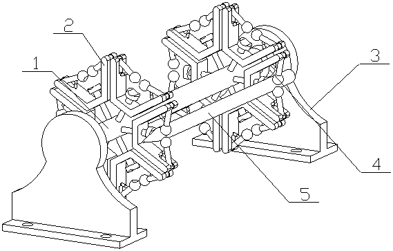
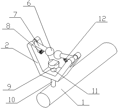
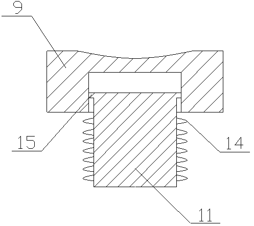
[0019] A numerical control tool placement frame of the present invention is realized in this way: a numerical control tool placement frame of the present invention consists of a central column (1), a support frame (2), a fixed seat (3), a bearing (4), and a fixed ball (6) , rotating rod (7), fixed boss (8), placing platform (9), connecting column (10), support rod (11), tension spring (12), pressure spring (14) and limit ring (15) The two ends of the central column (1) are respectively connected by bearings (4) and two fixed seats (3), the two fixed seats (3) are parallel, and the fixed seats (3) are provided with The fixing hole, the fixing seat (3) is narrow at the top and wide at the bottom, multiple sets of the connecting columns (10) are fixed on the side of the central column (1), the number of the connecting columns (10) is at least three groups, more The groups of connecting columns (10) are equidistantly distributed in a ring, and each group of connecting columns (10)...

Embodiment 2

[0023] The difference between this embodiment and Embodiment 1 is: there are multiple sliding grooves (13) on the outer surface of the central column (1), which correspond to multiple sets of connecting columns (10), and the sliding grooves (13) ) extends axially along the central column (1), and a sliding block is placed on the other end of the connecting column (10), and the sliding block is placed in the corresponding sliding groove (13); during use, the two in a group can be adjusted The distance between the two support frames (2) is suitable for CNC tools (5) of different lengths;

[0024] The fixed seat (3) is designed with a narrow top and a wide bottom, the bottom support is more stable, the support area is large, and the upper part can place a longer tool without being limited by the distance between the two fixed seats (3);

[0025] The other end of the support rod (11) is designed with a limiting convex ring, and the limiting groove is designed with a limiting bar n...


PUM


Abstract

The invention discloses a NC tool rack, which can avoid rigid collision between the NC tool and the rack when picking and placing a NC tool, and can be applied to NC tools of different lengths and shapes, wherein both ends of a central column are respectively connected with two fixing seats through bearings, the two fixing seats are parallel to each other and are provided with fixing holes, the fixed seats are narrow at the top and wide at the bottom, multiple sets of connecting columns are fixedly placed on the side of the central column, there are at least three sets of the connecting columns, multiple sets of the connecting columns are equally distributed in a ring shape, each set of the connecting columns is composed of two connecting columns, the middle of a support frame is connectedto one ends of the connecting columns, both ends of the support frame are bent upward to extend to form a support groove, one end of a support rod is fixedly placed on the groove wall of the supportgroove, and the other end of the support rod is provided with a limit convex ring.

Description

technical field [0001] The invention relates to a numerical control tool placement rack, which relates to a numerical control tool placement rack, and belongs to the field of mechanical equipment; in particular, it relates to a numerical control tool that can avoid rigid collision with the placement rack when picking and placing a numerical control tool, and is applicable to different lengths, CNC tool holder for shape CNC tools. Background technique [0002] Machining machine tools need to use CNC tools, and the CNC tools are placed in a fixed CNC tool rack for storage. The existing CNC tool rack is to directly insert the CNC tool into the CNC tool hole of the corresponding CNC tool rack. Because it is rigid The plug-in structure, when the CNC tool is taken out, the hole wall will collide with the CNC tool, and the surface of the tool bar of the CNC tool will be scratched, which will affect the machining accuracy of the subsequent CNC tool installed on the spindle of the CN...

Claims


Application Information

Patent Timeline
IPC IPC(8): B25H3/04B23Q13/00
CPCB23Q13/00B25H3/04
Inventor 不公告发明人
Owner 徐州易尚饰家装饰工程有限责任公司
Why Eureka
Try Eureka