
Material conveying mechanism and material conveying method

A technology of material transfer and conveyor belt, which is applied in the assembly field of the workshop transportation line, and can solve the problems of easy wear and tear of the conveyor belt

Inactive Publication Date: 2020-07-07
SHANGHAI WAIGAOQIAO SHIP BUILDING CO LTD
View PDF8 Cites 0 Cited by
  • Summary
  • Abstract
  • Description
  • Claims
  • Application Information

AI Technical Summary

Problems solved by technology

[0003] The technical problem to be solved by the present invention is to provide a material transmission mechanism and a material transmission method in order to overcome the defect that the lifting mechanism directly lifts the workpiece onto the conveyor belt in the prior art and causes the conveyor belt to be easily worn.

Method used


Image

  • Material conveying mechanism and material conveying method
  • Material conveying mechanism and material conveying method
  • Material conveying mechanism and material conveying method

Examples


Embodiment Construction

[0041] The present invention is further illustrated below by means of examples, but the present invention is not limited to the scope of the examples.

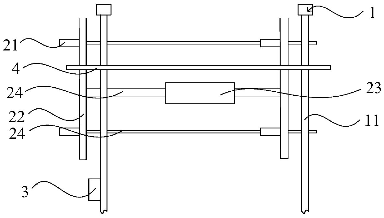
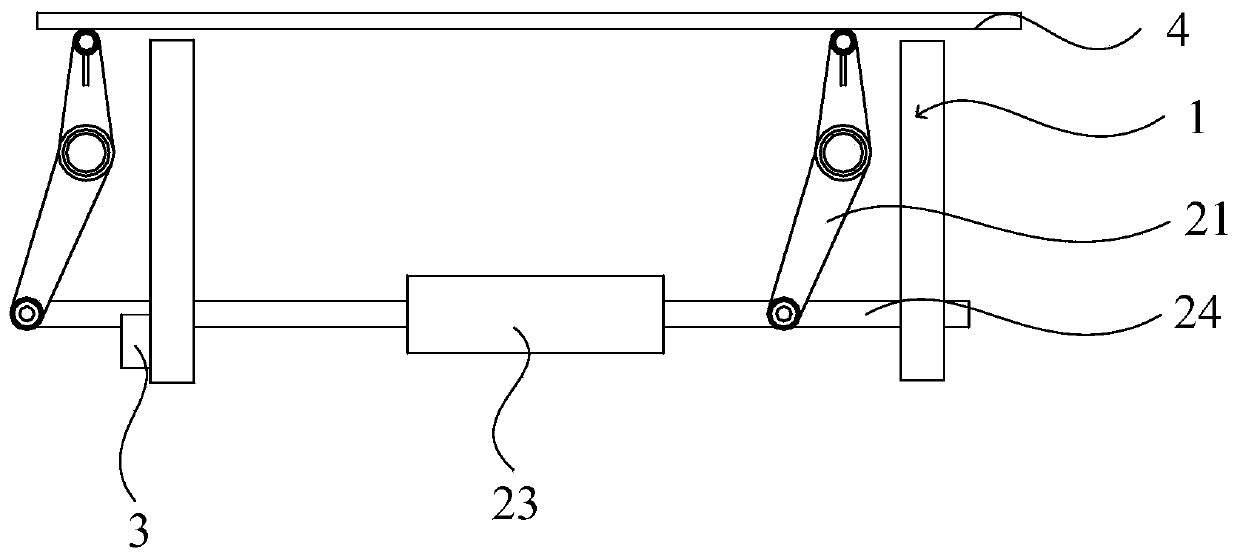
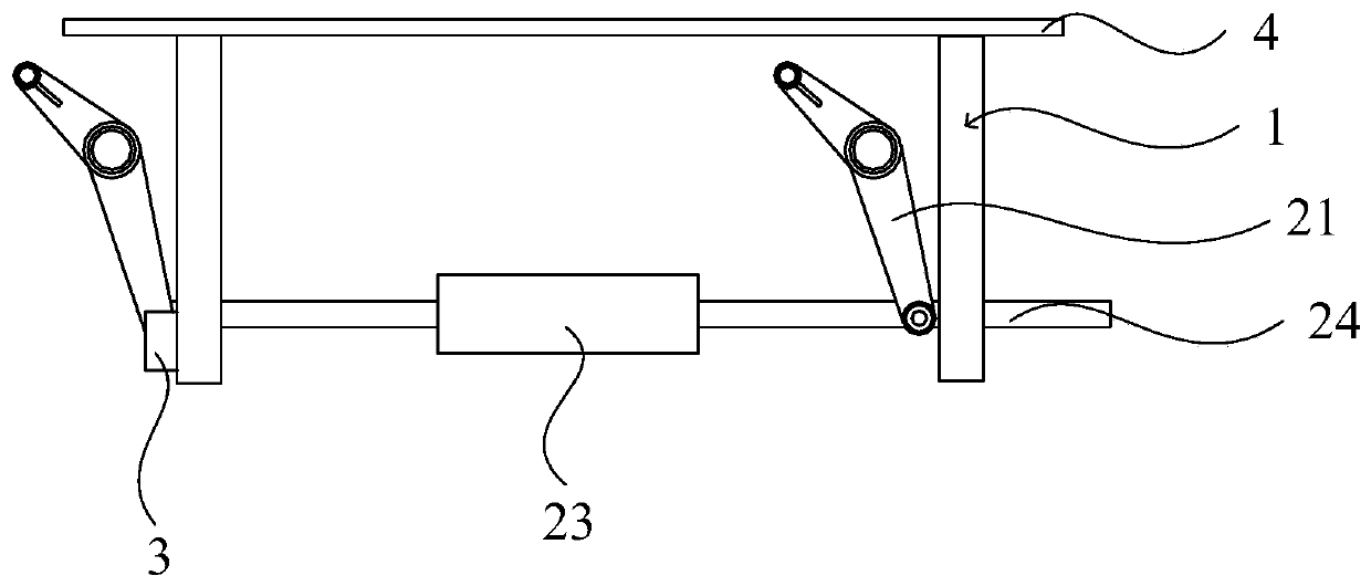
[0042] This embodiment provides a material transfer mechanism, which is used for the transfer of workpieces, and is especially suitable for the transfer of long workpieces. Such as Figure 1-3 As shown, the feeding mechanism includes a conveying device, a lifting device and a control device 3 .

[0043] The conveying device includes a plurality of conveying assemblies 1 arranged at intervals along the direction perpendicular to the conveying device's conveying direction, any conveying assembly 1 includes a conveying belt 11, and the conveying belt 11 can rotate cyclically. It should be noted that the specific structure of the conveying device and the method of rotating the conveying belt 11 belong to the prior art in the field, and will not be repeated here.

[0044] The lifting device is arranged close to the conveying devi...


PUM


Abstract

The invention discloses a material conveying mechanism and a material conveying method, and the material conveying mechanism and the material conveying method are used for conveying workpieces. The material conveying mechanism comprises a conveying device, a lifting device and a control device, wherein the conveying device comprises a conveying belt; the lifting device is arranged close to the conveying device and used for driving the workpieces to lift, and the control device is used for controlling the lifting device to lift; when the lifting device ascends to the highest position, the highest position of the lifting device is higher than the top end of the conveying belt; and when the lifting device descends to the lowest position, the highest position of the lifting device is lower than the top end of the conveying belt. A control assembly firstly controls the lifting device to ascend, so that the highest position of the lifting device is higher than the top end of the conveying belt, so that it is guaranteed that workpieces cannot make contact with the conveying belt when placed on the lifting device, the workpieces are prevented from being directly placed on the conveying device, abrasion of the conveying device is reduced, and the service life of the conveying device is prolonged; and then the control assembly controls the lifting device to descend, and the workpieces are moved to the conveying device.

Description

technical field [0001] The invention relates to the assembly field of a delivery line in a workshop, in particular to a material transfer mechanism and a material transfer method. Background technique [0002] In the production workshop of the factory, the conveying mechanism is generally used on the conveying line to convey the workpiece to the designated position. A common transmission mechanism is a plurality of transmission racks with conveyor belts. In the prior art, the workpiece is usually lifted directly onto the conveyor belt by a lifting mechanism, and then the workpiece is driven to a designated position by the conveyor belt. However, long-term use is likely to cause wear on the conveyor belt and affect the normal transmission of the workpiece. Contents of the invention [0003] The technical problem to be solved by the present invention is to provide a material transfer mechanism and a material transfer method in order to overcome the defect that the lifting m...

Claims


Application Information

Patent Timeline
Patent Type & Authority Applications(China)
IPC IPC(8): B65G47/06
CPCB65G47/06B65G2207/48
Inventor 何汉武孙宗峰严俊杨庆乔春节
Owner SHANGHAI WAIGAOQIAO SHIP BUILDING CO LTD
Learn More